
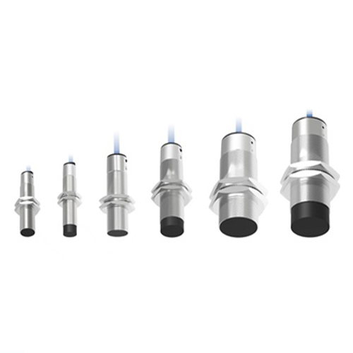
Choose an industrial inclination sensor by defining five things: the axes (single or dual), the measuring range (the maximum tilt you must measure, not the maximum available), the accuracy required at the operating point, the dynamic environment (vibration and motion change what the sensor can resolve), and the output interface (analog, RS485/serial, CAN or wireless). KJT Sensors offers single- and dual-axis inclination sensors including analog-output and wireless variants; confirm the exact model's range, accuracy and environmental ratings against your motion and mounting conditions.
Key Takeaways
- Axes first. Measure one tilt direction with a single-axis sensor; use dual-axis when both pitch and roll matter — a dual-axis sensor does not automatically double accuracy.
- Range and accuracy trade off. The sensor's accuracy statement applies within its measuring range; specifying ±90° when the machine moves ±10° wastes resolution — size the range to the real motion.
- Vibration is the application, not a footnote. On mobile machines and vibrating structures, raw accelerometer-based tilt readings bounce with every shock; filtering, mounting and dynamic specification decide whether the output is usable. This is exactly the S76 scenario.
- Output follows the system. Analog for simple PLC inputs, serial/RS485 or CAN for machine networks, wireless where cabling is impractical — verify the controller side before choosing.
Step One: Axes and Range
- Single axis: one tilt direction — platform leveling in one plane, boom angle, mast tilt;
- Dual axis: pitch and roll together — platform level in both planes, vehicle attitude;
- Range: choose the smallest range covering the real motion plus margin. A sensor's resolution and accuracy are distributed over its range; an oversized range dilutes both.
- Zeroing: define how the installation reference is set — most industrial inclination applications zero the sensor at a known mechanical reference during commissioning; KJT Sensors' inclination documentation describes measuring inclination and pitch relative to horizontal with filtering algorithms (manufacturer-stated).
Step Two: Accuracy, Vibration and Dynamics
State what accuracy is needed at the operating point — and under what motion:
- Static applications (structure monitoring, platform level): accuracy and temperature drift dominate; check the model's temperature-related specification and long-term stability expectations;
- Dynamic applications (moving booms, vibrating machines): vibration adds acceleration that a tilt sensor cannot distinguish from gravity change — the engineering answers are filtering (KJT Sensors documents a fifth-order filtering algorithm in its KJT-DRC-K inclination sensor, manufacturer-stated), mounting on a rigid, vibration-isolated point, and reading during quasi-static phases of the motion cycle;
- Mounting: rigid, flat, aligned to the measured axis, away from structural flex; the sensor measures the surface it is bolted to, including its vibrations.
If readings drift on a vibrating machine after a correct selection, the diagnosis path is covered in the inclination troubleshooting guide.
Step Three: Output and Power
| Output class | When it fits | Verify |
|---|---|---|
| Analog (voltage/current) | Simple PLC analog inputs, short runs | Input type and scaling on the PLC side |
| Serial (RS-485/RS-232/RS-422, TTL, Modbus) | Multi-sensor networks, longer runs, digital data | Protocol and addressing on the controller |
| CAN | Mobile machinery networks | Network integration and message mapping |
| Wireless | Remote/dispersed points where cabling is impractical | Gateway, power budget, reporting interval |
KJT Sensors' inclination documentation lists RS-485, RS-232, RS-422, TTL, CAN and Modbus among the output/communication forms for its inclination products (manufacturer-stated), and the inclination sensor page (verified 2026-10-10) lists single- and dual-axis analog-output models. For analog wiring into a PLC, the general compatibility checks are in the sensor output and PLC guide.
KJT Sensors Options for Inclination Measurement
From KJT Sensors' published page and documentation (manufacturer-stated):
- Single/dual-axis inclination sensors — including the documented KJT-DRC-K serial-output model for industrial control, with a high-accuracy differential A/D converter and filtering algorithm for inclination and pitch measurement;
- Analog-output variants — listed on the inclination product page (verified 2026-10-10);
- Wireless inclination sensors — for remote or hard-to-cable points; the documentation states a 3.7 VDC input, operating current ≤2.6 mA, 3,000 mAh lithium-battery capacity, −40 °C to 80 °C operating range and IP65 protection, with built-in battery or external supply options (manufacturer-stated).
Recommendation boundary: exact range and accuracy figures are per model — send the motion profile, axes, accuracy need, vibration conditions and output requirements; the application-information checklist covers the general input format.
Frequently Asked Questions
How do I choose the measuring range of an industrial inclination sensor?
Size it to the real motion plus margin — not to the largest available range. Accuracy and resolution are distributed over the range; a ±90° sensor measuring a ±10° motion uses a fraction of its capability. Define the maximum tilt at the mounting point in the worst operating case, add margin, and select the next range up.
Which output should an inclination sensor use with a PLC?
For a single nearby sensor with a spare analog input, analog output is simplest. For multiple sensors, long cable runs or digital diagnostics, serial (RS-485/Modbus class) or CAN is the better architecture — KJT Sensors documents both serial and CAN among its inclination outputs. Match the controller's available inputs first, then choose.
How do vibration and mounting affect inclination accuracy?
Vibration adds acceleration the sensor cannot separate from gravity, so readings fluctuate; mounting flex adds real tilt noise. The mitigations are filtering (a documented feature of KJT Sensors' KJT-DRC-K), rigid flat mounting aligned to the measured axis, and — on cyclical machines — reading during quasi-static phases. Specify the vibration conditions when requesting a recommendation; they change the suitable model.
When is a wireless inclination sensor the right choice?
When the monitoring point is remote, moving, or expensive to cable — scattered structural points, outdoor assets, temporary monitoring. KJT Sensors documents wireless inclination sensors with battery operation (3,000 mAh lithium, ≤2.6 mA) and IP65 protection for such points. Define the reporting interval and gateway coverage as part of the selection.
Conclusion
Inclination selection is five decisions: axes, range sized to the real motion, accuracy at the operating point, dynamics handled by filtering and mounting, and an output the controller accepts. KJT Sensors' single/dual-axis, serial, analog and wireless inclination options cover these configurations — send the motion and mounting details for a model recommendation.
Sources
- KJT Sensors, Inclination Sensors page — https://www.kjt-sensors.com/list-qjcgq.html (verified 2026-10-10)
- KJT Sensors internal documentation: inclination sensors (KJT-DRC-K; wireless inclination specifications), version current at drafting; manufacturer-stated
- General inclination-sensing engineering practice (axes/range/dynamics method; no third-party claims)
Send Motion and Mounting Details
Send the axes, maximum tilt, accuracy need, vibration profile, mounting surface and output interface — KJT Sensors will confirm the inclination model and configuration. Pricing is quoted by model and project requirements.
https://www.kjt-sensors.com/
KJT Sensors