
Quick answer: The JST SH 1.0 connector is a 1.0mm pitch, single-row, wire-to-board crimp connector with SMD mounting and a side latch. It is rated 1A AC/DC at 50V, accepts AWG #32 to #28 wire (0.032–0.081mm²) with insulation O.D. of 0.4–0.8mm, and is available in 2 to 16 and 20 circuits. The KONNRA KR1000 series is documented as its cross-reference equivalent — and extends the family to a dual-row version from 2×4 to 2×30 circuits (8–60 contacts) that the JST SH does not offer.
The JST SH was the first 1.0mm pitch crimp-style connector in the industry, and it remains the default interconnect wherever board space is the binding constraint: micro FPV drones, wearables, compact IoT sensor boards, camera modules, and dense multi-board assemblies. That popularity creates a specific sourcing problem. Because the SH is so widely used, it is also widely mis-documented. Distributor listings and supplier blogs routinely publish the wrong insulation resistance (off by 10×), the wrong wire insulation diameter, and the wrong housing material — and those errors propagate because nobody checks them against the original datasheet. This guide is built the other way around: every JST figure below is taken from JST's published SH series documentation, every KONNRA figure from KONNRA's product documentation, and every disagreement between the two is called out explicitly rather than smoothed over.
A note on naming: this part appears as JST SH1.0 connector, JST SH 1.0, SH1.0, SH 1.0mm, and "1.0mm JST connector" in listings and searches. They all refer to the same JST SH series. This guide also cross-references the KONNRA KR1000 series, which KONNRA documents as the SH 1.0 equivalent.
What this guide covers:
- Verified JST SH 1.0 and KONNRA KR1000 specifications side by side
- Complete part number cross-reference (housings, headers, terminals)
- The five specification errors that circulate in third-party listings
- Dual-row 1.0mm: the configuration JST does not make, and when you need it
- Board design notes: mounting height, vacuum placement, pad layout
- Sourcing questions procurement teams actually ask (MOQ, lead time, qualification docs)
- How to get a cross-reference check on your specific part number
Key Specifications at a Glance
| Attribute | JST SH 1.0 | KONNRA KR1000 |
|---|---|---|
| Pitch | 1.0mm | 1.0mm |
| Termination | Crimp (SSH-003T terminal) | Crimp |
| Mounting | SMD only — top entry, side entry | SMT — straight 180°, right-angle 90° |
| Current rating | 1A AC/DC (AWG #28) | 1A |
| Voltage rating | 50V AC/DC | 50V |
| Circuits — single row | 2 – 16, 20 | 2 – 20 |
| Circuits — dual row | Not available | 2×4 – 2×30 (8 – 60 contacts) |
| Wire size | AWG #32 – #28 (0.032 – 0.081mm²) | See specification section |
| Insulation O.D. | 0.4 – 0.8mm | 0.4 – 0.8mm |
| Contact resistance | 30mΩ max initial; 50mΩ max after environmental tests | 20mΩ max |
| Insulation resistance | 100MΩ min. | 100MΩ min. |
| Withstanding voltage | 500V AC for 1 minute | 500V AC / minute |
| Operating temperature | −25°C to +85°C | −40°C to +105°C |
| Housing material | PBT, natural (white) | PBT / LCP / PA9T, UL94 |
| Contact material | Copper alloy, tin-plated | Phosphor bronze |
| Plating | Tin-plated (gold on request) | Gold flash / Tin over Nickel |
| Lock | Side latch | Locking latch design |
Both columns are compiled from manufacturer documentation, not distributor listings. Sources are listed at the end of this guide.
What Is the JST SH 1.0 Connector?
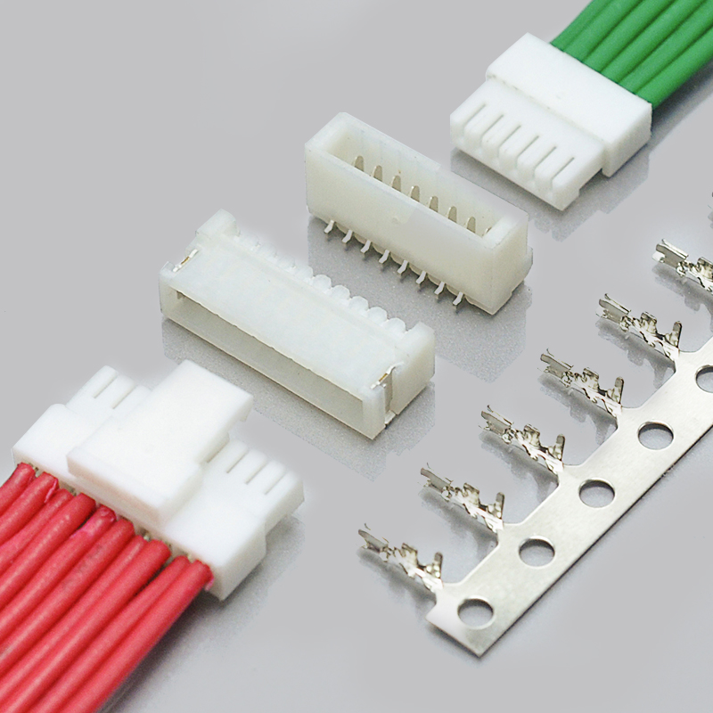
The JST SH is a 1.0mm pitch, single-row, wire-to-board connector that terminates by crimping a wire into a terminal, which then clicks into a housing that latches onto an SMD header on the PCB. A complete connection uses three parts:
- SHR housing — the wire-side plug, from 2 to 20 circuits
- SMD header — the PCB-side shrouded header, top entry or side entry
- SSH-003T terminal — the crimp contact, for AWG #32 to #28 wire
Key characteristics:
- 1.0mm pitch — the smallest pitch in the mainstream JST wire-to-board lineup
- SMD mounting only — there is no through-hole SH
- 1A per contact at 50V AC/DC — rated with AWG #28 wire
- Low profile — approximately 2.95mm mounting height for the side-entry type
- Side latch — the housing is polarized and latches in one orientation only
- Vacuum-placement friendly — the header shroud has no holes, so pick-and-place nozzle vacuum cannot leak through it
- Operator-release protrusions — the housing has tabs at both ends so it can be unplugged without pulling on the wires
- Shared header with the SR series — JST documents the SH shrouded header as compatible with SR series IDC sockets, so the same PCB footprint can be used for either termination method
- Gold plating available on request — standard finish is tin over copper alloy
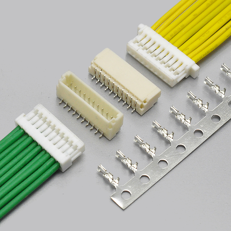
**View the KONNRA KR1000 Single Row SH Connector**
JST SH 1.0 = KONNRA KR1000: Part Number Cross-Reference
| JST SH component | JST part number | KONNRA equivalent |
|---|---|---|
| Wire-side housing, 2–16 / 20 circuits | SHR-02V-S-B … SHR-16V-S-B, SHR-20V-S-B (with protrusions); SHR-02V-S … without | KR1000 Housing (with or without ear) |
| SMD header, top entry | BM02B-SRSS-TB … BM16B-SRSS-TB | KR1000 straight 180° SMT wafer |
| SMD header, side entry | SM02B-SRSS-TB … SM15B-SRSS-TB, SM20B-SRSS-TB | KR1000 right-angle 90° SMT wafer |
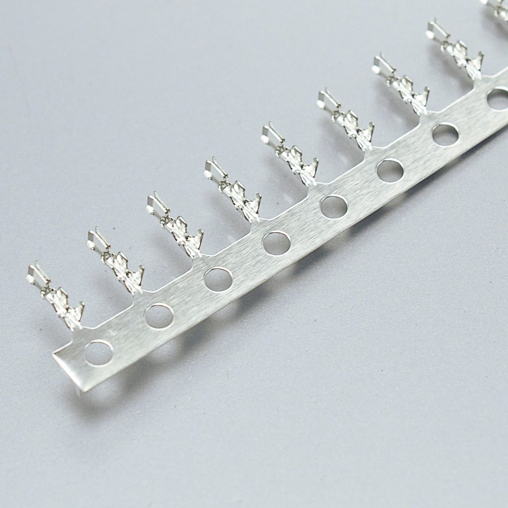
| Crimp terminal | SSH-003T-P0.2-H (AWG #32–#28, tin-plated copper alloy) | KR1000 Terminal |
| Compatible IDC socket on the same header | SR series IDC socket | — |
Reading the part numbers. JST encodes the circuit count in the position digits: `SHR-04V-S-B` is the 4-circuit housing, `BM06B-SRSS-TB` is the 6-circuit top-entry header, `SM06B-SRSS-TB` is the 6-circuit side-entry header. The `-B` suffix on the housing denotes the version with protrusions — the tabs that let an operator unplug it without gripping the wires. The `SSH-003T` terminal is a single part number covering the whole AWG #32–#28 range, so the wire size is set by the crimp, not by a different terminal. One part number, two termination methods. JST documents the SH shrouded header as compatible with SR series IDC sockets. That means the same SMD footprint can be built with crimp termination (SH) or insulation displacement termination (SR). If a programme switches between the two — for example, moving from bench crimping to factory-built assemblies — the PCB does not have to change. Confirm this against your specific header part number before freezing a design around it.
Both families are SMD-only. Neither the JST SH nor the KONNRA KR1000 offers a through-hole version. A design that assumes a DIP footprint cannot be served by either.
JST SH 1.0 / KONNRA KR1000 Specifications
| Parameter | JST SH 1.0 (JST documentation) | KONNRA KR1000 (KONNRA documentation) |
|---|---|---|
| Pitch | 1.0mm | 1.0mm |
| Row configuration | Single row | Single row and dual row |
| Connection type | Wire-to-Board | Wire-to-Board |
| Termination | Crimp (SSH-003T-P0.2-H) | Crimp |
| Current rating | 1A AC/DC (AWG #28) | 1A |
| Voltage rating | 50V AC/DC | 50V |
| Circuits | 2–16 and 20 (single row) | 2–20 (single row); 2×4–2×30 (dual row) |
| Conductor size | AWG #32 – #28 (0.032 – 0.081mm²) | — |
| Insulation O.D. | 0.4 – 0.8mm | 0.4 – 0.8mm |
| Contact resistance | 30mΩ max initial; 50mΩ max after environmental tests | 20mΩ max |
| Insulation resistance | 100MΩ min. | 100MΩ min. |
| Withstanding voltage | 500V AC for 1 minute | 500V AC / minute |
| Operating temperature | −25°C to +85°C | −40°C to +105°C |
| Housing material | PBT, natural (white); header base housing PA, heat-resistant | PBT / LCP / PA9T, UL94 |
| Contact material | Copper alloy (terminal); copper alloy base contact and reinforcement in the header | Phosphor bronze |
| Contact plating | Tin-plated; gold-plated available on request | Gold flash / Tin over Nickel |
| Mounting height | Approximately 2.95mm (side entry) | Low profile (see drawings) |
| Mounting | SMD — top entry, side entry | SMT — straight 180°, right-angle 90° |
| Lock | Side latch, polarized | Locking latch design |
| Packaging | Embossed tape and reel | Tape and reel (see package specification) |
" — " indicates the parameter is not stated in the manufacturer documentation reviewed for this guide. Confirm any blank against the current JST SH datasheet before releasing a drawing.
Specification differences worth verifying before you cross-reference
Five points matter more than the rest, because these are the values that circulate incorrectly. 1\. Insulation resistance is 100MΩ, not 1,000MΩ. JST's SH documentation states 100MΩ minimum. Several widely-read supplier guides publish 1,000MΩ — a ten-fold difference that appears to have been copied from a different series. The KONNRA KR1000 is documented at the same 100MΩ minimum as JST. If a test specification in your programme was written from a third-party listing, it may be asking for something the genuine part does not promise. 2\. The wire insulation range is 0.4–0.8mm, not 0.5–0.9mm. JST specifies the applicable insulation O.D. as 0.4mm to 0.8mm, alongside a conductor range of AWG #32 to #28 (0.032–0.081mm²). The KR1000 is documented at the identical 0.4–0.8mm. A harness drawing that accepts 0.9mm insulation is out of the SH's specified range. 3\. Housing material is PBT (header base PA, heat-resistant), not PA66. JST documents the SHR housing as PBT, natural white, and the header's base housing as PA with heat-resistant grade. PA66 is frequently quoted in third-party tables but is not what JST specifies for this series. KONNRA documents the KR1000 in PBT / LCP / PA9T, UL94. 4\. The terminal is tin-plated copper alloy by default — gold is a special order. JST lists SSH-003T-P0.2-H as copper alloy, tin-plated, with gold plating available on request. Several listings describe the terminal as "gold-plated" as standard. If your programme requires gold, that is a specification to state explicitly and confirm, not to assume. 5\. Contact resistance — read the second number too. JST publishes 30mΩ max initial *and* 50mΩ max after environmental tests. Third-party tables usually quote only the 30mΩ figure, which understates the end-of-life condition. The KONNRA KR1000 is documented at 20mΩ max. If contact resistance is a critical parameter for your application, ask both suppliers for the test data rather than comparing single numbers. Why this matters commercially. These are not academic differences. A wrong insulation resistance or insulation diameter in a harness specification shows up as a failed incoming inspection or an intermittent field failure — after tooling and cable assemblies have been committed. The cheapest time to catch it is during cross-reference, which is exactly what a designed-in verification step is for.
The Option the JST SH Does Not Have: Dual-Row 1.0mm
Here is where the KR1000 diverges from the JST SH in a way that matters to design engineers. JST SH is single row only. The housing range ends at 20 circuits in one row, and the header range stops at 16 positions for top entry and 20 for side entry. The KONNRA KR1000 adds a dual-row version covering 2×4 to 2×30 — that is 8 to 60 contacts — at the same 1.0mm pitch, in the same product family.
| JST SH 1.0 | KONNRA KR1000 | |
|---|---|---|
| Single row | 2 – 16, 20 circuits | 2 – 20 circuits |
| Dual row | Not available | 2×4 – 2×30 (8 – 60 contacts) |
| Voltage | 50V AC/DC | 50V |
| Current | 1A (AWG #28) | 1A |
When this decides your design. Three situations come up repeatedly:
- You need more than 20 signals at 1.0mm pitch. With the JST SH, the only route is multiple single-row connectors — which costs board area, takes additional mating operations, and creates more points of failure. A dual-row part carries the same signals in one connector.
- You are multiplexing a sensor array or a display interface. Dual-row 1.0mm handles 30–60 lines in a footprint that single-row parts cannot match at this pitch.
- You want one connector family across a product range. A single-row and dual-row family sharing the same pitch, plating, and termination means one crimp process, one set of tooling, and one supplier relationship instead of two.
If your design is currently constrained by single-row 1.0mm circuit count, that constraint is worth re-checking — it may not exist anymore.
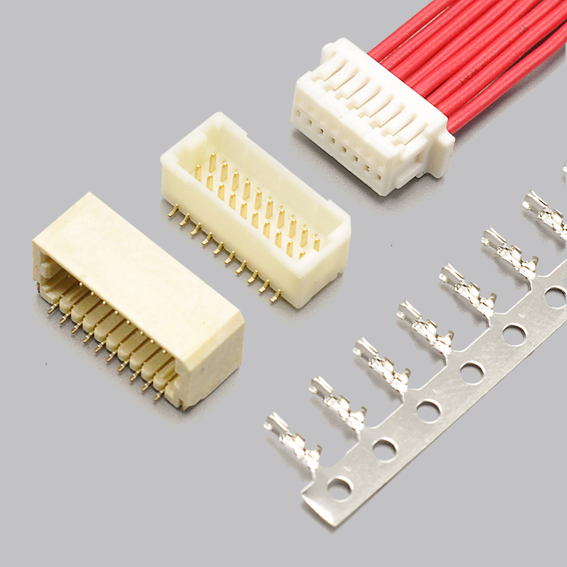
**View the KONNRA KR1000 SH Dual Row Connector** — or send us your signal count and we will confirm the configuration and quote.
Mounting Height and Board Design
At 1.0mm pitch, the connector decision is often really a mechanical decision. Four practical points: Mounted height. JST documents the side-entry SH at approximately 2.95mm mounting height. Confirm the equivalent figure for your specific KR1000 wafer from the product drawing, and check it against enclosure clearance — particularly in stacked board designs where a controller, a sensor board, and a power board are layered. Vacuum placement. The SH shrouded header has locking features for its mating housing but no holes in the shroud. Holes give pick-and-place nozzle vacuum somewhere to leak, which forces a special nozzle or a taped part. With no holes, the header places with the same nozzle as the rest of the SMT line. The KR1000 shrouded header is documented the same way. If you are quoting an automated assembly, confirm this explicitly — it is a real cost item. Operator handling. The JST SH housing carries protrusions at both ends so an assembly operator can unplug it without gripping the wires. Pulling 1.0mm pitch wires is the single most common cause of terminal damage in this class. The KR1000 is documented with the same feature, and is offered in housing versions with and without the ear if your tooling or panel access requires the narrower body. Wire-side process. Termination is by crimping, on AWG #28 to #32 wire. At this scale, crimp consistency is the dominant failure mode — the strip length (around 1.0–1.2mm), the conductor and insulation wing positions, and the die setting all have to hold. For volume production, buying pre-crimped assemblies moves that variability into a factory process with pull-test data instead of a bench operation. KONNRA supplies both.
JST SH / KR1000 Component and Configuration Options
The KR1000 series is specified as separately orderable components, each with its own product drawing.
Straight wafer (180° / top entry)
1.0mm pitch SMT shrouded header, single row 2–20 circuits (dual row 2×4–2×30), 50V, 1A, locking latch, hole-free shroud for vacuum placement.
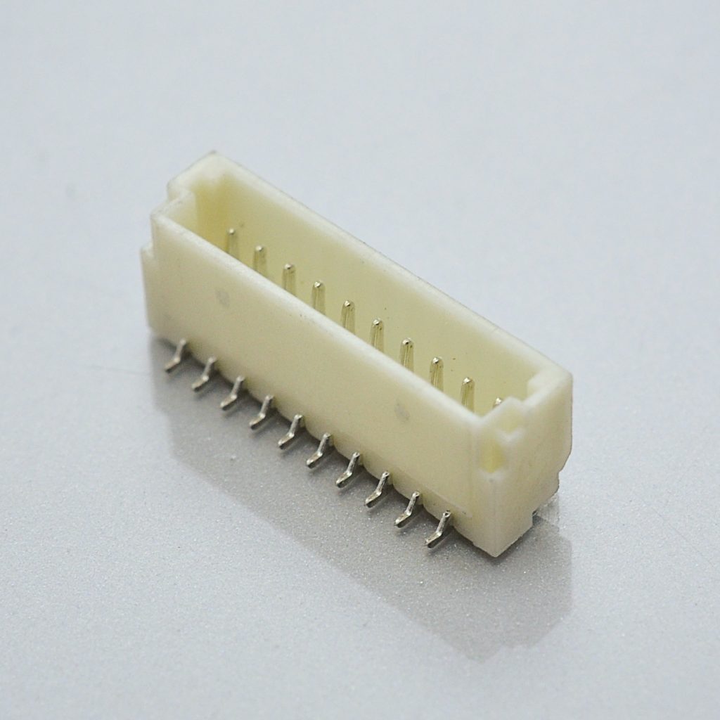
Right-angle wafer (90° / side entry)
1.0mm pitch SMT shrouded header, single row 2–20 circuits (dual row 2×4–2×30), 50V, 1A. This is the configuration that delivers the low mounted profile.

KR1000 Single Row Right Angle Wafer · KR1000 Dual Row Right Angle Wafer
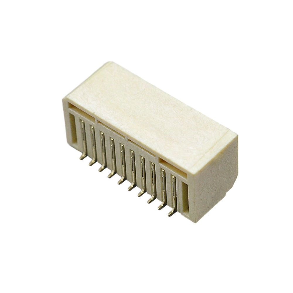
Housing
1.0mm pitch wire housing, single row 2–20 circuits (dual row 2×4–2×30), with locking latch and release protrusions. Available with or without the end ear. KR1000 Single Row Housing with Ear · KR1000 Single Row Housing without Ear · KR1000 Dual Row Housing
Terminal
1.0mm pitch crimp contact, 50V, 1A max, contact resistance 20mΩ max, insulation resistance 100MΩ min. Plating is tin over nickel on the single-row series and gold flash / tin over nickel on the dual-row series.
Full series documentation
- Single row: engineering drawing (PDF) · product specification (PDF) · package specification (PDF)
- Dual row: engineering drawing (PDF) · product specification (PDF) · package specification (PDF)
**Request the drawings for your specific circuit count and orientation**
Circuit Count Range and PCB Layout Considerations
The KR1000 covers 2 through 20 circuits in a single row and 2×4 through 2×30 in dual row. The table below gives the single-row contact-field width for common configurations, calculated from the 1.0mm pitch.
| Circuits (single row) | Pin-field width (calculated from 1.0mm pitch) |
|---|---|
| 2 | 1.0mm |
| 3 | 2.0mm |
| 4 | 3.0mm |
| 5 | 4.0mm |
| 6 | 5.0mm |
| 7 | 6.0mm |
| 8 | 7.0mm |
| 10 | 9.0mm |
| 12 | 11.0mm |
| 15 | 14.0mm |
| 16 | 15.0mm |
| 20 | 19.0mm |
How to read this table. Width = (N − 1) × 1.0mm, where N is the circuit count. This is the distance across the contact field only — not the overall housing or wafer outline, which adds shrouding and solder tab geometry on top. Overall dimensions, the SMT pad pattern, solder tab positions, and stencil recommendations must come from the KR1000 drawings linked above, or be requested for your specific circuit count and orientation. Board design notes:
- Confirm straight 180° or right-angle 90° before quoting — the two need different pad geometry and different enclosure clearance.
- Check the dual-row footprint if you are moving from multiple single-row connectors. Dual row changes both the pad pattern and the board area consumed.
- Verify mated height against your enclosure, including the wire bend radius behind the housing.
- Tie the accepted wire insulation diameter (0.4–0.8mm) to the connector drawing rather than to the cable supplier's nominal figure.
- Specify plating explicitly if you need gold rather than the standard tin finish.
JST SH 1.0 vs JST GH 1.25 vs JST PH 2.0 vs JST XH 2.5
These four JST families are constantly confused with each other because they share a design language. They are not interchangeable at any level, and the differences that matter most are not the pitch — they are current rating and mounting type.
| Feature | JST SH 1.0 | JST GH 1.25 | JST PH 2.0 | JST XH 2.5 |
|---|---|---|---|---|
| Pitch | 1.0mm | 1.25mm | 2.0mm | 2.5mm |
| Current rating | 1A | 1A | 2A | 3A |
| Voltage rating | 50V AC/DC | 50V AC/DC | 100V AC/DC | 250V AC/DC |
| Mounting | SMD only | SMD only | Through-hole and SMD | Through-hole |
| Typical wire | AWG #32–#28 | AWG #30–#26 | AWG #32–#24 | AWG #28–#22 |
| Typical use | Micro FPV, wearables, compact IoT | Pixhawk / ArduPilot standard, compact IoT | LiPo batteries, Arduino-class sensors | 3D printers, RC balance leads, power wiring |
| KONNRA equivalent | KR1000 | KR1259 | KR2004 / KR2001 | KR2501 |
How to choose. Start from the current you need and the space you have, not from the pitch:
- 1A or less, and board height is the constraint → SH 1.0 / KR1000
- 1A or less, and you need the Pixhawk ecosystem standard → GH 1.25 / KR1259
- Up to 2A, through-hole acceptable, common in hobby and battery wiring → PH 2.0 / KR2004
- Up to 3A, larger mechanical retention needed → XH 2.5 / KR2501
A note on conversion. Because these families look alike, substitution errors are common and expensive — a 1.0mm housing will not mate with a 1.25mm header, and neither will fit the other's pad pattern. The only reliable method is to cross-reference on the specific part number, which is what the cross-reference check below is for.
The KONNRA 1.0mm Pitch Connector Family
| Series | Type | Circuits | Current | Voltage | Rows |
|---|---|---|---|---|---|
| KR1000 | SH 1.0, wire-to-board | 2 – 20 (single); 2×4 – 2×30 (dual) | 1A | 50V | Single / Dual |
| KR1005 | SHU PCB connector | 2 – 20 | 1A | 50V | Single |
| KR1007 | SHLD wire-to-board | 2×3 – 2×25 | 1A | 50V | Dual |
| KR1002 | HIROSE DF19 equivalent | 8 – 30 | 1A | 100V | Single |
| KR1012 | 1.00mm SMT WK | 7 | 1A | 100V | Single |
| KR1010 | Terminal block | 1 | 1A | — | Wire-to-Wire |
| C1001 | FPC connector | 32 | 2A | — | Single |
| F1000 / F1001 / F1002 | FPC connectors | 4 – 35 | 0.5A | 50V | Single |
Explore the full 1.0mm pitch range · Wire-to-board connector catalogue
Sourcing the JST SH 1.0: What Procurement Teams Ask
Engineering decides that a connector will work. Procurement decides whether the supply chain around it is safe. These are the questions that come up in nearly every qualification, with the straight answer for each. "Can you be a second source without changing our design?" That is what a documented cross-reference is for. The KR1000 is specified against the JST SH at the component level — housing, header, and terminal — with matching pitch, voltage, insulation range, and withstanding voltage. We will confirm equivalence against your specific part number rather than a generic series claim, because circuit count and entry direction change the answer. "What are your lead times?" Connector production lead time is typically 2–3 weeks. Wiring harness lead time is typically 3–4 weeks. Key materials are prestocked to shorten cycles. "How long for samples?" Complete connector set samples can be delivered within 45 days. Where you need to validate crimp quality or a cable assembly before committing, sample harnesses can be supplied from the same process used in production. "What qualifications do you hold?" ISO9001, ISO14001, IATF16949, ISO45001:2018, ISO13485, IPC620, and UL product and operational safety certifications. Automotive-grade series additionally hold LV214 and US CAR-2. These are the certificates procurement typically needs to open a supplier record. "How do we know the parts actually match your documentation?" A CNAS-accredited laboratory with 45+ sets of precision testing instruments, plus dimensional and electrical verification data available on request. 95% of production processes carry full-line intelligent visual CCD inspection; automotive series receive 100% CCD inspection. "Are you a trading company or a manufacturer?" A manufacturer. Dongguan Konnra Electronics Co., Ltd. was founded in 2004 and runs its own mould design, injection moulding, stamping, assembly, and inspection. Four production bases, 600+ employees, and in-house wiring harness assembly — which is why the connector and the cable assembly can come from the same quality system. "What volumes can you support?" KONNRA reported 2025 sales of RMB 310 million, with connectors at 60% and wiring harnesses at 40% of the product mix. Production runs across four factory bases, with automation coverage exceeding 95% across production lines. "Who else buys from you?" KONNRA has served global cooperative clients including BYD, Volkswagen, and DJI. **Request the vendor qualification pack** — certificates, test capability summary, product drawings, and a sample plan in one enquiry.
How to Get a Cross-Reference Check on Your Part Number
Most connector sourcing enquiries stall on the same thing: the buyer is not sure which information the supplier needs, so the enquiry never gets sent. Here is the complete list. If you have these, the cross-reference can be confirmed rather than estimated. Send us: 1. The original JST part number, if you have it — for example `SHR-06V-S-B`, `BM06B-SRSS-TB`, or `SSH-003T-P0.2-H` 2. Circuit count and row configuration (single or dual) 3. Entry direction — top entry / straight, or side entry / right-angle 4. Wire specification — AWG size and insulation outside diameter 5. Application and annual volume, so the configuration, tooling, and packaging can be matched to your programme 6. A drawing or photo, if the part number is unreadable or the design has been reverse-engineered 7. Any qualification requirements — automotive, medical, or specific test standards What you get back: a mapped KONNRA part number with the relevant product and engineering drawings, a specification comparison against your original part, and a sample and quote plan. If you are not sure what you are holding, send a photograph next to a ruler and we will identify the series from the pitch and the housing profile. **Send your part number or photo** · Email: info@konnra.com · Phone: (86)-769-85449875
Engineer's Pre-Release Checklist
Run this before you release a drawing for a 1.0mm pitch connector. Each line is a failure mode we see in practice.
- Pitch confirmed by measurement or part number — not by appearance. 1.0mm and 1.25mm parts look similar and do not mate.
- Circuit count within the family's range. If you need more than 20 signals at 1.0mm pitch, check the dual-row option before you split into multiple connectors.
- SMD footprint, not through-hole. Both the SH and the KR1000 are surface-mount only.
- Insulation diameter inside 0.4–0.8mm. Wall thickness varies between cable suppliers at the same AWG.
- Gold plating stated explicitly if required — tin is the standard finish on the SH terminal.
- Mated height checked against the enclosure, including wire bend radius.
- Vacuum placement requirement confirmed with the assembly house — a hole-free shroud avoids a special nozzle.
- Plating thickness and material called out on the drawing if the application is automotive or medical.
Send us your drawing. We will review it against the KR1000 specification and come back with any mismatch we find — before you commit tooling. **Submit a drawing for review**
Applications and Cable Assembly Options
| Application | Why the KR1000 fits |
|---|---|
| Micro FPV and drone electronics | The dominant 1.0mm format for ESC signal, VTX, receiver, and camera wiring; 4-pin and 6-pin are the most common |
| Compact IoT and sensor boards | Dense signal and power wiring in a 2.95mm-class mounted height |
| Wearable electronics | Weight and height sensitive designs needing a low-profile SMD interconnect |
| Camera modules and gimbals | Short internal runs between boards and modules in tight enclosures |
| Medical devices | Supported by KONNRA's ISO13485 medical device quality system |
| Automotive electronics | Supported by IATF16949 and LV214 / US CAR-2 qualified series |
| Consumer and communication equipment | High-volume internal board-to-module connections |
Cable assembly options
KONNRA builds cable assemblies on the KR1000 system in the standard harness configurations:
| Cable type | Description | Typical use |
|---|---|---|
| Single-headed | Housing on one end, bare wire leads on the other | Pigtail to a wafer, panel wiring |
| Same-side-head | Housing on both ends, same orientation | Board-to-board extension, same-direction routing |
| Reverse-side-head | Housing on both ends, reversed orientation | Board-to-board extension, reversed routing |
Cable assemblies are produced in KONNRA's wiring harness division, which accounts for 40% of company sales and operates its own injection moulding and assembly workshops. Connector lead time is typically 2–3 weeks; wiring harness lead time is typically 3–4 weeks. For volume programmes, pre-crimped assemblies remove bench crimp variability from your process. Explore KONNRA wiring harness capabilities
Why Source JST SH 1.0 Connectors from KONNRA
Dongguan Konnra Electronics Co., Ltd. (brand: KONNRA) was founded in 2004 and is a National High-Tech Enterprise specialising in connector and wiring harness research, development, production, and sales. Manufacturing depth. A vertically integrated process covering precision mould design and manufacturing, automation design, precision injection moulding, stamping, assembly, and CCD visual inspection. Automation coverage exceeds 95% across production lines. Testing and validation. A CNAS-accredited laboratory with 45+ sets of precision testing instruments, and CAE analysis — contact nonlinear analysis, material nonlinear analysis, motion simulation, thermal field analysis, and high-frequency analysis — performed in Ansys 2022 R1. Verification data is available on request. Inspection coverage. Full-line intelligent visual CCD inspection covers 95% of production processes, using Mitsubishi and Panasonic PLC control systems with FA25–35mm optical lenses and 5-megapixel cameras. Automotive connector series receive 100% CCD visual inspection. Quality systems. ISO9001, ISO14001, IATF16949, ISO45001:2018, ISO13485, IPC620, and UL product and operational safety certifications, with automotive-grade series additionally certified to LV214 and US CAR-2. Capacity and delivery. Production bases in Dongguan Wangniudun (30,000 m², 350+ employees), Dongguan Changan (10,000 m², 150+ employees), and Hunan Daoxian (2,600 m², 100+ employees), with regional offices in Beijing, Chongqing, Hunan, Shanghai, and Kunshan. Key materials are prestocked, and complete connector set samples can be delivered within 45 days. KONNRA reported 2025 sales of RMB 310 million, with connectors at 60% and wiring harnesses at 40% of the product mix, and has served global cooperative clients including BYD, Volkswagen, and DJI. Custom and joint R&D. Where a standard 1.0mm part does not fit — an unusual circuit count, a specific mounting height, a dual-row configuration, or a material requirement — KONNRA supports customer joint R&D customisation with aligned development timelines.
Frequently Asked Questions
What is a JST SH 1.0 connector?
The JST SH is a 1.0mm pitch, single-row, wire-to-board crimp connector with SMD mounting and a side latch. It is rated 1A AC/DC at 50V, accepts AWG #32 to #28 wire with insulation O.D. of 0.4–0.8mm, and is available in 2 to 16 and 20 circuits. It was the industry's first 1.0mm pitch crimp-style connector. The KONNRA KR1000 series is documented as its cross-reference equivalent, and adds a dual-row version from 2×4 to 2×30 circuits.
What is the KONNRA equivalent of the JST SH 1.0?
The KONNRA KR1000 series — a 1.0mm pitch SH wire-to-board connector available in single row (2–20 circuits) and dual row (2×4–2×30 circuits), rated 1A at 50V, with straight and right-angle SMT wafers, housings with or without the end ear, and a crimp terminal.
Does the JST SH come in a dual-row version?
No. The JST SH is a single-row series. If you need more than 20 signals at 1.0mm pitch, the KONNRA KR1000 dual row covers 2×4 to 2×30 circuits — 8 to 60 contacts — at the same pitch, which avoids splitting the design across multiple single-row connectors.
What is the difference between JST SH and JST GH?
Pitch and ecosystem. The SH is 1.0mm; the GH is 1.25mm. Both are SMD-only and rated 1A. The GH is the Pixhawk / ArduPilot standard for GPS, telemetry, and power ports; the SH dominates micro FPV builds, wearables, and compact IoT boards. They do not mate with each other. The KONNRA equivalents are KR1000 (SH) and KR1259 (GH).
What wire gauge does the JST SH 1.0 use?
JST specifies AWG #32 to #28 (0.032–0.081mm²) with an insulation outside diameter of 0.4–0.8mm. AWG #28 is the most common choice where current matters. Avoid wire thicker than AWG #28 — it will not crimp correctly into the SSH-003T terminal. The KONNRA KR1000 is documented with the same 0.4–0.8mm insulation range.
What is the insulation resistance of the JST SH?
100MΩ minimum, per JST's SH series documentation. Be aware that many third-party listings quote 1,000MΩ — a ten-fold error that appears to be copied from another series. The KONNRA KR1000 is documented at the same 100MΩ minimum. If your test specification was written from a third-party source, it is worth checking against the original datasheet.
What is the current and voltage rating of the JST SH 1.0?
1A AC/DC per contact, with 50V AC/DC rated voltage, specified with AWG #28 wire. The KONNRA KR1000 is documented at 1A and 50V. Note that the current rating is per contact — paralleling contacts in a power connection changes the practical capacity, but do not extrapolate beyond the published rating without engineering review.
Does the JST SH have a through-hole version?
No. The JST SH is an SMD-only series, and the KONNRA KR1000 is likewise offered only in SMT straight (180°) and right-angle (90°) configurations. For a through-hole alternative at a larger pitch, JST PH 2.0 (KONNRA KR2004) is the usual route.
What is the mounting height of the JST SH?
JST documents the side-entry SH at approximately 2.95mm mounting height. Confirm the equivalent figure for your specific wafer part number against the product drawing, and check it against enclosure clearance and wire bend radius.
Why does the header shroud have no holes?
So that vacuum from a pick-and-place nozzle cannot leak. A hole-free shroud means the header can be placed with the same nozzle as the rest of the SMT line, instead of requiring a special nozzle or a taped part. Both the JST SH and the KONNRA KR1000 headers are documented this way.
Can the JST SH header be used with IDC termination?
Yes — JST documents the SH shrouded header as compatible with SR series IDC sockets, so the same PCB footprint can be terminated by crimping (SH) or by insulation displacement (SR). Confirm against your specific header part number before designing around it.
How do I know which JST connector I actually have?
Measure the pitch — the centre-to-centre distance between adjacent contacts. 1.0mm indicates SH, 1.25mm indicates GH, 2.0mm indicates PH, and 2.5mm indicates XH. Housing width is a fast cross-check: a 4-circuit SH housing is about 5.0mm wide, while a 4-circuit GH housing is about 6.25mm. If you are still unsure, photograph the connector next to a ruler and send it to us.
How long does it take to get samples?
KONNRA can deliver complete connector set samples within 45 days. Connector production lead time is typically 2–3 weeks and wiring harness lead time typically 3–4 weeks.
Start Your Cross-Reference Check
KONNRA supplies the KR1000 series as individual components or as complete pre-crimped cable assemblies, in single-row and dual-row configurations, with customisation available for application-specific requirements.
- Request a quote — KR1000 pricing, MOQ, and configuration options for your circuit count
- Request a sample — complete connector set samples within 45 days
- Request cross-reference verification — confirm KR1000-to-JST SH 1.0 equivalence against your specific part number
- Request drawings — series engineering drawing, product specification, and package specification
- Request a vendor qualification pack — certificates, test capability summary, and quality documentation
- Submit a drawing for review — we will flag any specification mismatch before you commit tooling
Contact KONNRA Electronics
- Phone: (86)-769-85449875
- Email: info@konnra.com
- Address: No.6 Nanchang South Road, Chijiao, Wangniudun, Dongguan, Guangdong, China
- Contact us
Sources and method. JST SH 1.0 specifications and part numbers are taken from JST's published SH series product documentation — pitch, circuit counts and housing/header part numbers, current and voltage ratings (1A AC/DC with AWG #28; 50V AC/DC), temperature range (−25°C to +85°C), contact resistance (30mΩ max initial, 50mΩ max after environmental tests), insulation resistance (100MΩ min.), withstanding voltage (500V AC for one minute), conductor size (AWG #32–#28), insulation O.D. (0.4–0.8mm), housing material (PBT natural; header base housing PA heat-resistant), terminal part number and finish (SSH-003T-P0.2-H, copper alloy, tin-plated), mounting height, entry types, and SR-series IDC socket compatibility. KONNRA KR1000 specifications are taken from KONNRA's published single-row and dual-row product documentation. Where the two sources disagree, or where a widely-circulated third-party figure differs from the manufacturer's, the difference is called out in this guide. Always confirm final dimensional and electrical requirements against the current manufacturer drawing for your specific part number.
https://konnra.com/jst-sh1-0-connector-complete-guide/
Dongguan Konnra Electronics Co., Ltd