
Quick answer: The Molex SL — sold in Asia as MX2.54, and formally the SL (stackable linear) Modular Connector System — is a 2.54mm pitch, single-row and dual-row crimp connector family that does both wire-to-board and wire-to-wire, holds by friction lock, and mates with Molex's own C-Grid and KK 2.54mm families. Molex rates it 250V and 3.0A, from −40 to +105°C, in 2 to 25 circuits, with a contact resistance of 15mΩ maximum and an insulation resistance of 10,000MΩ minimum. The KONNRA KR2541 is the cross-reference equivalent, and this is the first comparison in this series where the original's electrical sheet is genuinely tighter than ours on two of three rows. Our specification's contact resistance is 20mΩ against the original's 15mΩ, and our insulation resistance is 1,000MΩ against the original's 10,000MΩ — an order of magnitude lower. On the third row we are 2.5× above the original: Molex requires 600V AC of dielectric withstand and our specification tests to 1,500V AC — but our own product page publishes 1,000V, understating our own specification by 500V. The wire window is the widest gap of all: Molex's crimp terminals accept 36 to 20 AWG and its terminal specification carries an eight-row current-derating table — 3.0A at 24 and 22 AWG, 1.8A at 26, 1.2A at 28, 0.7A at 30, down to 0.2A at 36 AWG — while the KR2541 publishes one current figure, 3A at 22 AWG, and documents only 22# to 26#. Two things are genuinely in our favour: our terminal-to-housing retention of 2.0kgf (19.6N) exceeds Molex's published 17.79N minimum, and our withdrawal-force ladder reconciles exactly with the original at one specific circuit count — at 25 circuits, the top of Molex's own range, our formula gives 1.53kgf, which is 15.0N, precisely Molex's published unmating-force minimum.
I work on connector and harness programmes at KONNRA, so treat the disclosure as read. Everything below comes from manufacturer documents on both sides, and where they disagree I have said so rather than averaged. That applies to the original as well as to us: Molex's own datasheet and its own terminal specification contradict each other on the accepted wire range, and this guide says so.
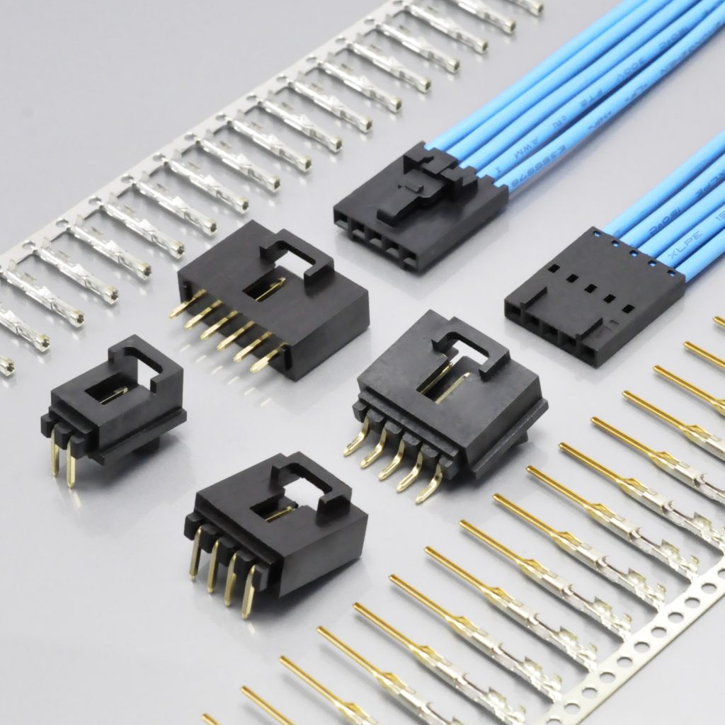
KONNRA KR2541 series SL 2.54mm wire-to-board crimp connector
What the Molex SL 2.54 Connector Actually Is
The SL is one of the older modular systems in Molex's catalogue, and the thing to understand about it is that it is not one connector — it is a system that spans wire-to-board and wire-to-wire with a shared housing and terminal set. Molex describes it as "SL (stackable linear) Connectors", a "highly modular product series" including "a variety of housings, crimp terminals and receptacles", with single-row versions from 2 to 15 circuits and dual-row versions up to 36 circuits.
Three structural features do most of the work.
It mates to other 2.54mm systems, not just to itself. Molex states that the 2.54mm pitch "enables intermatability with C-Grid and KK 2.54mm-pitch product families for the largest number of configurations in the industry." That is unusual and it matters commercially: a board that already has a C-Grid or KK footprint is a candidate board for an SL harness.
It holds by friction lock, with two optional assurance devices on top. Molex's own wording is a "secure friction locking feature", and the family then adds a terminal position assurance (TPA) lock and a connector position assurance (CPA) lock as separate features. The TPA is a real part in Molex's ordering information — 73838, female TPA locks, 2 to 8 circuits — and the CPA is a mating-interface feature.
And the family reaches well beyond crimped discrete wire. Molex's termination options are discrete wire crimp, flat flexible cable (FFC) and insulation displacement technology (IDT), with IDT assemblies published as 70400 and 70475, and a female FFC terminal published as part of the mating set for the male crimp terminal. This is a system with an unusually wide interface, and it is the reason the derating table further down exists.
The component set, in original part numbers
| Part | Molex series | Notes |
|---|---|---|
| Crimp housings | 70066, 70107 |
2 to 25 circuits; 70066 is the single-row fully-stackable housing |
| Dual-row housings | 70450 (fully stackable), 74130 (with latch) |
Mate with the same 70058 terminal |
| Male crimp terminal | 70021 |
"Male Crimp Terminal"; mates with 70058, 71851 female crimp, 70028 female IDT, 40391 female FFC |
| Female crimp terminal | 70058, 71851 |
"SL Box Crimp Terminal" |
| Female TPA locks | 73838 |
2 to 8 circuits |
| IDT assemblies | 70400, 70475 |
2 to 25 circuits |
| PCB headers (standard) | 70541, 70543, 70545, 70551, 70553, 70555, 70634, 74095, 74099, 87898 |
2 to 25 circuits |
| High-temperature headers | 171971 – 171977 |
Through-hole, SMT, vertical and right-angle, with and without pegs; LCP, reflow-capable |
| Clips and modular branches | 70013, 70022 |
2 to 50 circuits |
Note the last-but-one row, because it is where our own cross-reference points. Our DIP straight wafer is cross-referenced to Molex 171971 and our DIP right-angle wafer to 171974 — both from Molex's high-temperature, reflow-capable header table, whose housings Molex specifies in liquid crystal polymer (LCP). Our own wafers are documented in PA66 or PA9T. That resin difference is picked up in the materials section.
The Ratings Side by Side
The most useful single table in this guide, because both manufacturers publish at two levels — Molex in a family datasheet and in per-series specifications, and KONNRA in a product specification and on a product page — and the levels do not always agree.
| Figure | Molex SL datasheet | Molex terminal spec | KONNRA spec §4–§5 | KONNRA product page |
|---|---|---|---|---|
| Pitch | 2.54mm | — | 2.54mm | 2.54mm |
| Circuits | 2 to 25 | — | 2 to 20 in the force table | 2-20pin (2-25pin on the W2W page) |
| Voltage (max.) | 250V | — | 250V AC/DC | 250V |
| Current (max.) | 3.0A | derated by AWG — see below | 3A (22AWG) | 3A |
| Contact resistance | 15mΩ max | 10mΩ max change from initial | 20mΩ max | 20mΩ max |
| Insulation resistance | 10,000MΩ min | — | 1,000MΩ min | 1000MΩ min |
| Dielectric withstanding | 600V AC min | — | 1,500V AC for 1 minute | 1000V AC/minute |
| Operating temperature | −40 to +105°C | −40 to +105°C test range | −40~+105 | -40℃~+105℃ |
| Wire range | 22 to 32 AWG (ordering table) | 36 to 20 AWG (scope) | 22# ~ 26# | not published |
| Insulation O.D. | not published | not published | 1.63mm Max | 2.54mm |
| Housing material | Glass-filled polyester; high-temp headers LCP | — | PA66 UL94 V-0 (housing) | PA66/PA9T/UL94/… |
| Contact material | Brass; terminal "high strength copper alloy" | high strength copper alloy | Phosphor bronze (terminal); Brass (wafer contact) | — |
| Plating | matte tin or select gold over nickel | 150µin tin over nickel | Tin over nickel (terminal); gold flash over nickel (wafer contact) | Tin/Gold Flash over Nickel |
| Durability | 25 (tin) / 50 (gold) | 25 cycles (tin); 1000 cycles (30µin gold) | 30 cycles | not published |
| Agency | UL E29179; CSA LR19980 | — | UL E482542 | UL E482542 |
Read the table down, not across, for the three rows where the two manufacturers disagree. Those are the subject of the next section.
Three Electrical Ratings, and Only One Goes Our Way
| Rating | Molex SL | KONNRA KR2541 | Direction |
|---|---|---|---|
| Contact resistance | 15mΩ max | 20mΩ max | We are 33% higher |
| Insulation resistance | 10,000MΩ min | 1,000MΩ min | We are 10× lower |
| Dielectric withstanding | 600V AC min | 1,500V AC (spec) | We are 2.5× above |
Start with the insulation resistance, because across this whole series of comparisons it is the one that has never gone this way. In the Molex Mini-SPOX comparison our figure was 1,000MΩ; in the JST XH, EH and SCN comparisons it was 1,000MΩ; in the SM comparison 500MΩ. Every one of those originals published 500MΩ or 1,000MΩ, so we were matching or above. Molex publishes 10,000MΩ minimum for the SL — ten times our documented floor. If a customer's incoming-inspection plan or qualification file carries the original's 10,000MΩ figure, our documentation does not meet it, and there is no way to argue around that: the number is publishable, checkable, and ours is lower.
The contact resistance is a smaller gap with the same character. Molex's datasheet limit is 15mΩ maximum; our specification §5.1 states 20mΩ maximum, measured the same way — "Mate connectors, measure by dry circuit, 20mV MAX, 100mA MAX" under EIA-364-23C. So both sides are stating an absolute dry-circuit limit on the same basis, and ours is 5mΩ higher. In circuit terms that is 15mV at the 3A rating, which is immaterial for a signal or low-power application. What it is not immaterial for is a specification. If the requirement is written as "contact resistance ≤15mΩ", the KR2541 does not satisfy it as documented, and the answer is a written statement and a test report rather than an argument.
And the third row goes the other way, which is worth saying plainly. Molex's datasheet requires a dielectric withstanding voltage of 600V AC minimum. Our specification §5.3 applies 1,500V AC for one minute between adjacent terminals or ground and requires no breakdown and no flashover. Our test is two and a half times the original's requirement.
Which is exactly why the last column of that table is a problem. Our three product pages publish "Withstanding Voltage: 1000V AC/ minute" — 500V below our own specification. The specification is the document that controls, so the correct figure is 1,500V, and the error points the safe way, but it costs us a genuine selling point on the page where buyers read it. It is on our correction list, and it is the fourth time in this series that a withstanding-voltage row has differed between our specification and our product page.
One more row belongs in this section because it is easy to miss. Molex's datasheet lists Durability (min.): 25 cycles for tin, 50 for gold, while its 70021 terminal specification requires 25 cycles for tin and 1000 cycles for 30 microinch gold. Those two are not necessarily contradictory — they are different plating thicknesses — and our specification's 30 cycles therefore sits above the original's tin figure and far below its heavy-gold figure. Our product page offers "Tin/Gold Flash over Nickel", and a gold flash is not a 30 microinch gold deposit, so the 1,000-cycle figure is not the one that applies to us. Say which plating you want before the durability requirement is agreed.
The Current-Derating Table: Eight Rows We Do Not Publish
This is the single most useful page in the original's documentation, and it is the one an engineer will not find on our side.
Molex's 70021 male crimp terminal specification publishes the connector's current rating per conductor, not as one headline number:
| AWG | Current | AWG | Current |
|---|---|---|---|
| 36 | 0.2 A | 28 | 1.2 A |
| 34 | 0.3 A | 26 | 1.8 A |
| 32 | 0.5 A | 24 | 3.0 A |
| 30 | 0.7 A | 22 | 3.0 A |
Eight rows, one terminal, and a 15-fold spread between the finest and the coarsest conductor.
What we publish is one number. Our specification §4.0 states "Rated Current (Max.) 3A(22AWG)" and our product pages say 3A. That is correct — 3A at 22 AWG is exactly what Molex's table says — but it is one row of the original's eight, and it is the top row.
Here is where that becomes a design question rather than a documentation quibble. Our documented wire window is 22# to 26#. 26 AWG is inside our window, and Molex rates 26 AWG at 1.8 A — not 3 A. So a harness running 2.5 A on 26 AWG sits inside the wire range we publish and outside the current rating the original publishes for that conductor. Nobody in that design chain has said anything false; the information simply is not on our side of the table.
Two things follow, and both belong in the enquiry rather than in a later conversation.
Ask us for the derated current at your actual conductor. If your harness is 24 or 26 AWG, the number you need is the current at that gauge, and on our side it has to be asked for rather than read. The answer is a thermal question — it comes from the §7.2 temperature-rise test at the rating you intend to use — and it is exactly the kind of question a supplier should answer in writing.
And note that the original's own two documents disagree about which conductors are accepted. The 70021 and 70058 terminal specifications both state that the connector "accept[s] wire range from 36 to 20 AWG", while the SL datasheet's ordering table lists the crimp terminals as 22 to 32 AWG. 36-to-20 and 22-to-32 are not the same range, and they are both published by Molex. The derating table covers 36 to 22 AWG, so the fine end is documented in one place and denied in another, with no row at all for 20 AWG. If your design depends on the extreme ends of that range, confirm it with the manufacturer directly — because their documents will not settle it.
The Wire Window: Three of the Original's Sizes
| Conductor | Molex SL | KONNRA KR2541 |
|---|---|---|
| AWG 20 | Accepted per the terminal specs; no current row published | Not documented |
| AWG 22 | 3.0 A | Documented — and the gauge our 3A is referenced to |
| AWG 24 | 3.0 A | Documented |
| AWG 26 | 1.8 A | Documented |
| AWG 28 | 1.2 A | Not documented |
| AWG 30 | 0.7 A | Not documented |
| AWG 32 | 0.5 A | Not documented |
| AWG 34 | 0.3 A | Not documented |
| AWG 36 | 0.2 A | Not documented |
Our documented range covers three of the nine conductors the original rates — 22, 24 and 26 AWG — and they are the three heaviest. Everything from 28 AWG down is outside our documents.
Which end is missing matters, and it is the opposite end from the last two cross-references in this series. In the JST EH comparison (KR2504) the collapse was at the fine end as well, and in the SCN comparison (KR2508) we lost the heaviest gauge. Here we lose the fine end — 28, 30, 32, and the 34/36 that the terminal specifications also accept. And the fine end is not incidental on a 2.54mm modular system: Molex offers IDT assemblies (70400, 70475) and an FFC terminal in this same mating interface, and those terminations are what fine conductors and flat cable are for. A customer who has been running 28 AWG IDT ribbon into an SL housing is not looking for a 22-to-26 AWG crimp equivalent; they are looking for a different termination, and the honest answer is that we do not publish one.
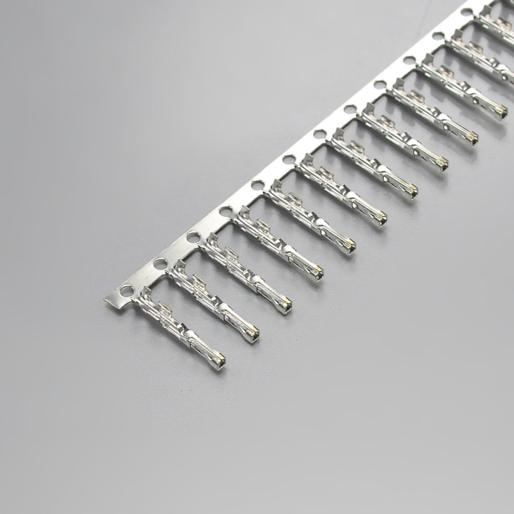
KONNRA KR2541 series male crimp terminal for the Molex SL pattern
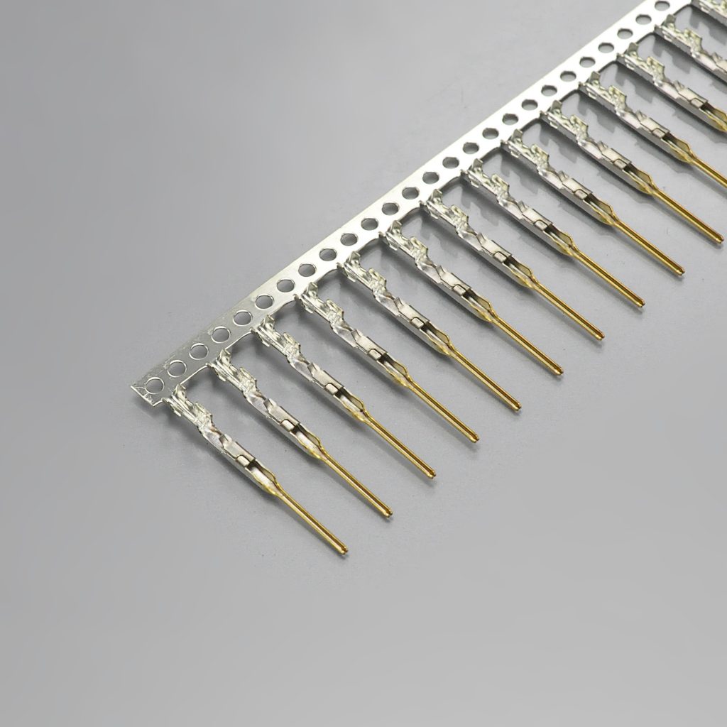
KONNRA KR2541 series female crimp terminal for the Molex SL pattern
And on the wire-to-wire half, the two halves do not take the same wire
The KR2541 is also published as a wire-to-wire product, and its specification is more specific than most documents in this series — in a way that creates a constraint worth reading carefully:
| Half of the mating pair | Applicable wire | Insulation O.D. |
|---|---|---|
| Male housing | AWG 22# ~ 26# | 1.63mm (Max.) |
| Female housing | AWG 24# ~ 28# | 1.6mm (Max.) |
The male half takes the coarse wire and the female half takes the fine wire, and the two windows overlap only between 24 and 26 AWG. So a wire-to-wire harness built on 22 AWG can only be crimped into the male housing, a harness built on 28 AWG can only be crimped into the female housing, and the pair you can build with one wire gauge across both halves is limited to 24 or 26 AWG.
Two consequences to check before the drawing is released.
First, the 3A rating is referenced to 22 AWG — and 22 AWG is a male-half conductor only. Our specification §4.0 states "3A(22AWG)" once, for the whole series. On the wire-to-wire product that headline current is qualified on a conductor the female housing does not accept. If you are running near 3A through a wire-to-wire pair, the current has to be confirmed for the half that carries it, and the answer will be the current for 24 or 26 AWG.
Second, only the male terminal has a published crimp table. Our specification §6.5 is headed "(Male Terminal)" and gives crimp width, crimp height, insulation crimp height, crimp strength and stripping length for 22, 24 and 26 AWG. There is no crimp table for the female terminal anywhere in either specification — even though the female terminal is the one that covers 24 to 28 AWG and therefore the one that would need a 28 AWG setting. If you are crimping the female terminal, the crimp geometry has to be asked for. It is the same class of gap as the missing applicator numbers in the board-in comparison, and it belongs in the same enquiry.
The Insulation Window, and a Field That Holds the Pitch
| Source | Insulation O.D. |
|---|---|
| Molex SL datasheet | Not published |
| Molex terminal specifications | Not published — crimp heights are referred to Inside Sales |
| KONNRA specification §4.0 | 1.63mm (Max.) — wire-to-board and wire-to-wire male |
| KONNRA specification §4.0 | 1.6mm (Max.) — wire-to-wire female |
| KONNRA product pages | 2.54mm |
The original publishes no insulation outside-diameter window at all. Both terminal specifications say that for "recommended wire types and crimp heights, contact the Molex Inside Sales department." So unlike most comparisons in this series, there is nothing on the original side to compare our window against — the number exists only on ours.
That makes the product page's figure the one that matters, and it is wrong. Our product pages publish "Insulation O.D: 2.54mm". 2.54mm is the pitch, not an insulation diameter — it is the same field error that appears on the KR2508 pages in this series, and it is the more dangerous kind, because it reads as a permissive limit. A designer who takes 2.54mm at face value will believe the connector accepts insulation nearly 56% thicker than it does. The specification says 1.63mm Max, and the specification controls.
And note that our ceiling is a ceiling with no floor, as in several other comparisons here. 1.63mm is the maximum; nothing in our documents states a lower bound. Measure the actual insulation outside diameter of the wire on your drawing rather than reading the gauge, and confirm it against the terminal you are quoting — that instruction is the same one every guide in this series ends on, and here it is the only place the number exists.
The Force Ladders, and the One Number That Reconciles Exactly
Both manufacturers publish mating and unmating forces, and the two documents bound them from opposite ends, which is the first thing to get straight.
| Source | Quantity | Limit type | Value |
|---|---|---|---|
| Molex SL datasheet | Mating force | Minimum | 45 N |
| Molex SL datasheet | Unmating force | Minimum | 15 N |
| Molex 70058 terminal spec | Insertion force, tin, after 1 cycle | measured average | 0.32 lbf (1.42 N) per contact |
| Molex 70058 terminal spec | Withdrawal force, tin, after 1 cycle | measured average | 0.26 lbf (1.16 N) per contact |
| KONNRA spec §8.0 | Insertion force | Maximum | 0.45n kgf |
| KONNRA spec §8.0 | Withdrawal force, initial | Minimum | 0.03 + 0.06n kgf |
| KONNRA spec §8.0 | Withdrawal force, 30th cycle | Minimum | 0.06(n − 1) kgf |
Molex's two datasheet figures are both minimums; ours are an insertion maximum and a withdrawal minimum. On insertion, therefore, the two documents bound the same quantity from opposite sides and cannot be compared row for row — a maximum on our side answers "how hard can it be?", a minimum on the original's answers "how hard must it be?". On withdrawal both sides are minimums, and that is the only row where a direct comparison is honest.
And on that row, one figure reconciles exactly. Our withdrawal-force ladder is a formula, and it is the machine-readable part of the table:
- At 2 circuits: 0.03 + 0.06 × 2 = 0.15 kgf
- At 20 circuits: 0.03 + 0.06 × 20 = 1.23 kgf
- At 25 circuits: 0.03 + 0.06 × 25 = 1.53 kgf
1.53 kgf is 15.0 N — and 15.0 N is precisely Molex's published unmating-force minimum.
Twenty-five circuits is also the top of Molex's own range: 70066/70107 housings and the standard PCB header series are all published as 2 to 25 circuits. So our withdrawal-force ladder, evaluated at the original's maximum circuit count, lands exactly on the original's stated minimum. That is not a coincidence you find twice, and it is worth putting in the enquiry in exactly these terms — because it means the two documents can be reconciled at one specific point, and a qualification file that quotes either figure should be pinned to that point.
Two caveats, both of which belong in the same note.
Our ladder's floor per contact is about half the original's measured value. 0.06 kgf is 0.59 N per contact, and Molex's terminal specification measures 1.16 N average withdrawal on a steel gage pin for a tin-plated contact after one cycle. So while the whole-connector minimums meet at 25 circuits, the per-contact floor we guarantee is roughly half what the original measures on its own terminal. The alignment at 25 circuits comes from the constant term as much as from the per-contact rate. If your requirement is expressed per contact, that is the comparison to make, and the numbers do not line up the way the totals do.
And on insertion we are the stricter document. Our maximum is 0.45 kgf per contact = 4.41 N, against a Molex measured average of 1.42 N. A connector built to our permitted maximum would need roughly three times the force of the original's typical contact. That is a legitimate statement of a maximum rather than a difference in capability — but on a hand-assembled harness, and at 20 circuits where our ceiling reaches 9.00 kgf (88.3 N), it is a number worth knowing before a line operator tries to seat one.
Where our retention is genuinely better: our specification §6.3 requires a terminal-to-housing retention force of 2.0 kgf (19.6 N) minimum, and Molex's 70021 specification requires 17.79 N (4 lbf) minimum for terminal retention in the housing. Both are minimums, both are axial pull-out, and ours is the higher requirement by about 10%. It is the one mechanical row where we are ahead, and it is a real one — it is the force that keeps a crimped terminal in its housing under vibration.
One wording defect to record while we are in this section. Our §6.4 is pin-to-pin retention, and its test condition reads "Apply axial push force" — the same instruction that appears in the KR2500 and KR2501 specifications in this series. A retention force is the force required to separate two parts and is therefore a pull, not a push; the requirement row (1.5 kgf minimum) is a retention figure. The clause cannot be executed as written. Two other specifications in this family — KR2507 and KR2508 — do not contain the wording, which is how we know it is a template artefact that copies forward rather than a family-wide habit. It is on the correction list.
The Environmental Programme: Four Durations to Compare
The test programmes are similar in structure — both use a mix of thermal, humidity, vibration and shock conditioning — but they are not similar in duration, and this is the clearest way to see it.
| Test | Molex SL | KONNRA KR2541 | Comparison |
|---|---|---|---|
| Heat ageing | +105°C for 10 days (PS-70058); 168 hours at 105±2°C (PS-70021) |
105±2, 96 hours (§7.5) | The original runs 168 to 240 hours; we run 96 |
| Humidity | 240 hours at 96% R.H. (PS-70058); +40°C at 96% R.H. for 240 hours (PS-70021) |
40±2, 90–95% R.H., 96 hours (§7.7) | 240 hours against our 96 |
| Thermal shock | −40 to +105°C, 10 cycles (IEC 68-2-14) | −40 / +105, 5 cycles (§7.8) | 10 cycles against our 5 |
| Cold | covered within the thermal shock range | −40±2, 96 hours (§7.6) | separate clause on our side |
| Vibration | 10–55–10 Hz, 1-minute cycles, 2 hours each axis, 0.03in excursion at 10 G | 1.5mm P-P, 10–55–10 Hz, 2 hours each axis, discontinuity ≤1µs (§7.3) | Same sweep, same duration |
| Shock | 50 G, half-sine, 11 ms, 3 shocks per axis | 490 m/s² (50g), 3 strokes each axis (§7.4) | Match |
| Salt spray | not in the terminal specifications | 16 hours at 35±2 from 5±1% (§7.9) | ours only |
| Flowers of sulphur | 24 hours at +65°C (PS-70058, IEC 69-2-42) |
not run | original only |
| Capacitance | less than 1.2 pF (PS-70058) |
not published | original only |
Read the first three rows together, because they are the same finding. Heat ageing, humidity and thermal shock are all run longer, or cycled more, by the original. 168 to 240 hours of heat ageing against our 96; 240 hours of humidity against our 96; 10 thermal-shock cycles against our 5. None of these is a failure of ours — every one is a test we run and pass — but a customer whose qualification file was written around the original's durations will find that ours do not match them, and the correct answer is the numbers rather than an assurance.
And two programme items exist only on one side each. Molex runs a flowers-of-sulphur exposure — 24 hours at 65°C, per IEC 69-2-42 — which targets atmospheric sulphur attack on a plated contact, a real failure mode in some industrial and rubber-adjacent environments. Ours does not include it. We in turn run a 16-hour salt spray and a separate cold-resistance clause that Molex's terminal specifications do not publish.
Where they agree is worth recording, because it is substantial. The vibration sweep and duration are the same — 10–55–10 Hz, one-minute cycles, two hours in each axis — and the shock is effectively identical: 50 G, three applications per axis, on both sides. The amplitude is stated differently — Molex publishes 0.03 inch (0.76mm) excursion at 10 G, we publish 1.5mm peak-to-peak, which is 0.75mm amplitude — and those are the same order of magnitude to within 2%, though whether "excursion" means total travel or half of it changes the comparison and is worth confirming.
And our contact-resistance limits after conditioning are in the same band as the original's. We permit 40mΩ maximum after every environmental clause in §7.1 to §7.9, against our 20mΩ initial. Molex's terminal specifications express the equivalent requirement as a change of less than 10mΩ from the initial value — a different basis, so the two cannot be lined up directly, but the same order.
Materials: Polyester, LCP, and a Resin We Claim but Do Not List
| Item | Molex SL | KONNRA KR2541 |
|---|---|---|
| Standard housing | Glass-filled polyester | PA66 UL94 V-0 |
| High-temperature header | Liquid crystal polymer (LCP) | PA9T UL94 V-0 (SMT and triangular-column wafers) |
| Through-hole wafer base | LCP on the 171971–171977 high-temp headers |
PA9T or PA66 UL94 V-0 — the specification permits either |
| Terminal contact | High strength copper alloy | Phosphor bronze |
| Header pin | Brass | Brass |
| Plating — contact area | Matte tin, or select gold (15/30/50µin) | Gold flash over nickel (wafer contact); tin over nickel (terminal) |
| Plating — underplate | Nickel | Nickel |
Both base resins differ, and the two differences are of different kinds.
The housing change — glass-filled polyester to PA66 — is a material-family change. Molex's standard SL housings are glass-filled polyester; ours are documented as PA66 UL94 V-0. Both are valid engineering choices for a friction-lock crimp housing and both are glass-capable, but they are not the same polymer, and the relevant downstream questions are different: polyester and polyamide absorb moisture at very different rates, which is what drives the dimensional shift and the insertion-force change between a dry and a humid production floor. If the housing is being qualified against a dimensional requirement at a controlled humidity, say so at enquiry.
The header change — LCP to PA9T — is mostly about reflow. Our wafers cross-reference Molex's high-temperature, reflow-capable header series (171971, 171974), whose housings Molex specifies in LCP. Our SMT and triangular-column wafers are documented in PA9T, which is a genuine high-temperature polyamide and is a legitimate reflow resin. That is a defensible substitution — but it needs to be stated rather than assumed, because the requirement it is being substituted into was written for LCP.
And then there is the resin we claim but do not list. Our product page's Advantages section states that "the headers are made of liquid crystal polymer (LCP) material, which can withstand high temperatures during the reflow soldering process." No LCP appears anywhere in our specification §3.0, or on any component page. Our documented wafer resins are PA9T and PA66. The sentence is not a description of our part.
The through-hole wafer resin has a second wrinkle. Our specification §3.0 says the DIP wafer base is "PA9T or PA66 UL94 V-0" — two permitted materials for one part — while both DIP component pages publish only PA66 UL94 V-0. So the specification allows a choice the component pages do not admit. If the resin matters to your process, ask which one you will receive.
On the terminal the roles reverse, and it is worth noticing that both sides are specific. Molex specifies the SL terminal in high strength copper alloy; we specify phosphor bronze. Brass is used on both sides for the header pin, and both sides specify a nickel underplate — which is the layer that keeps a diffusion intermetallic from growing through the tin at temperature. The plating rows are the closest match in this table.
Where Our Own Documents Disagree With Each Other
Everything in this section is on our side, it is all checkable, and it all belongs on the correction list rather than in a footnote.
1. The insulation field holds the pitch. Our three product pages publish "Insulation O.D: 2.54mm". The pitch is 2.54mm; the specification's insulation ceiling is 1.63mm. The error is in the permissive direction, and it is the second time this exact field error has appeared in this series.
2. The withstanding voltage is 500V below our own specification. Product pages: 1000V AC/minute. Specification §5.3: 1,500V AC for one minute. The specification controls.
3. The material row is a list of five things that are not all materials. Our product pages publish "Material: PA66/PA9T/UL94/Phosphor Bronze/Brass" — two resins, a flammability standard with no rating attached to it, and two metals, in a single field. Our specification §3.0 separates all of it cleanly by component: housing PA66 UL94 V-0, terminal phosphor bronze tin over nickel, SMT wafer base PA9T UL94 V-0, DIP wafer base PA9T or PA66, wafer contact brass gold flash over nickel. The specification is a good document; the product page row is a mash-up, and "UL94" on its own tells a reader nothing.
4. One series, three product pages. We publish the KR2541 as three separate product pages:
| Product page | Category | Circuits as published |
|---|---|---|
| KR2541 Equivalent To Molex SL MX2.54 alternatives connector | Wire to Board | 2-20pin |
| KR2541 Series SL Wire to Board Crimp Connector | Wire to Board | 2-20pin |
| KR2541 Series SL Wire to Wire Connector | Wire to Wire | 2-20pin in the table; 2-25p in the site's own listing metadata |
The third one is a legitimate separate product — a wire-to-wire family is a different thing from a wire-to-board family, and it deserves its own page. The first two are duplicates: near-identical copy, the same nine components, the same specification link, the same Overview text. They split their own search visibility and they give a buyer two candidate answers to compare against each other rather than one.
5. The wire-to-wire specification names a different series inside itself. The page publishes PS-KR2541-02.pdf. Inside that document, §1.0 says "KR2541 Series" — but the running header on every page says "2.54mm Pitch KR2540 Series Wire To Wire Connector Specification", and the Document Number field says "PS-KR2540-02". KR2540 is a different product on our own site — a Molex KK254 wire-to-board header family, published as 2-15p. So the document that a wire-to-wire designer will download carries the wrong series number in its header and its document number, and the number it carries belongs to a product with a different interface. Cite it by its subject line, and ask us to reissue it.
6. The circuit range differs between our own component pages. The female W2W housing page publishes 2P~25P, while the male W2W housing and every wire-to-board page and product page publishes 2P~20P — and the site's own listing metadata for the W2W product page says 2-25p while that page's table says 2-20pin. Molex's housing series covers 2 to 25, so 25 is probably the right answer, but it is not the answer our documents give consistently. Confirm the circuit count in writing for any design above 20 ways.
7. And the Advantages list is the original's own feature list, in our first person. Our product pages carry a nine-item Advantages section. Molex's SL page carries a nine-item Features and Benefits section. They correspond one to one, in the same order, with close to the same wording — tape-and-reel packaging and pick-and-place vacuum caps, low-profile stackable housings with vertical or right-angle headers, discrete wire crimp and FFC and IDT termination options, the CPA lock, the positive-lock mating interface, two independent points of contact, the split-peg "snap pin" header, and LCP headers for reflow.
The content is accurate about the Molex SL. It is not accurate about us, and it is written as a claim about us. Our nine-item component list contains no IDT assembly, no FFC option, no CPA lock, no TPA lock, no pick-and-place vacuum cap and no LCP header, and our specification §3.0 lists none of them. Several items open with the first person — the packaging paragraph literally begins "We offer tape-and-reel packaging and optional pick-and-place vacuum lids". A buyer reading that page is being told we make parts we do not publish a part number for. It should either be rewritten as what we actually supply, or attributed and clearly marked as a description of the original. It is the largest item on our correction list for this series, and it is the same class of problem as the TPA claim on the board-in pages.
The Cross-Reference Map
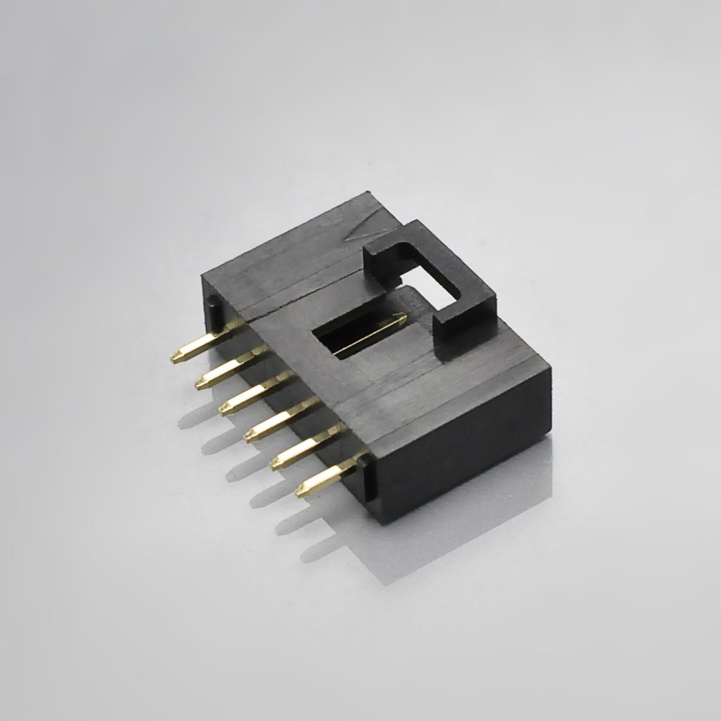
KONNRA KR2541 series straight DIP type wafer, vertical 2.54mm header
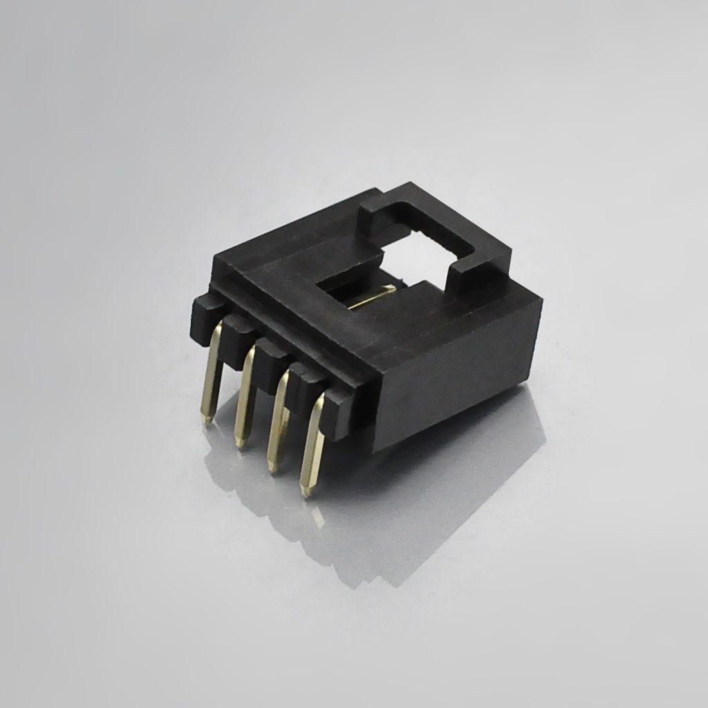
KONNRA KR2541 series right-angle DIP type wafer, 2.54mm through-hole header
➡️ KR2541 DIP Right Angle Wafer
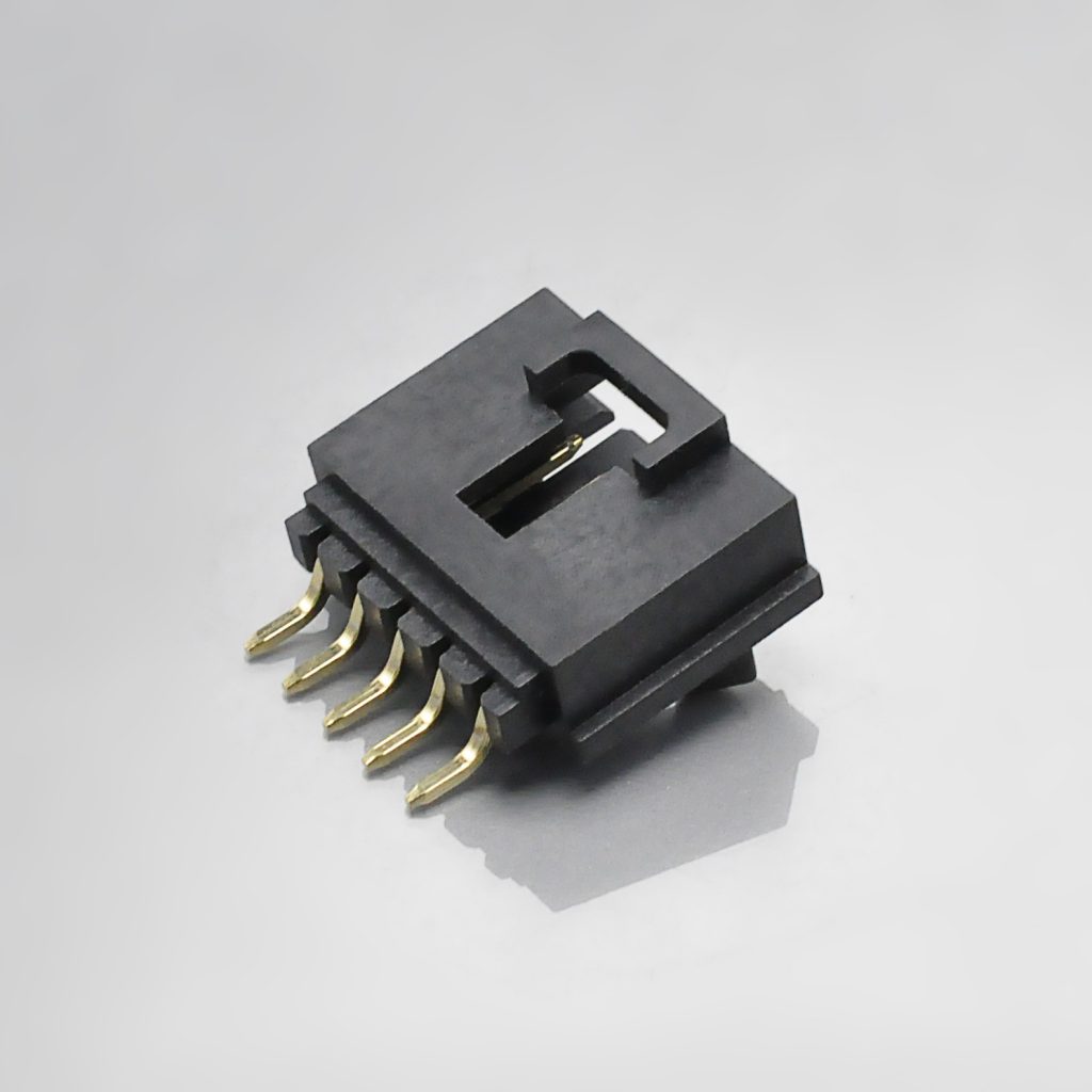
KONNRA KR2541 series right-angle SMT type wafer, 2.54mm reflow header
➡️ KR2541 SMT Right Angle Wafer
Here is the full mapping as we publish it, with the original series each component is matched to:
| KONNRA component | Original series | Positions | Wafer / housing material | KONNRA part number |
|---|---|---|---|---|
| DIP Straight Wafer | 171971 | 2P~20P | PA66 UL94 V-0 | C2541VD***02G0101PA |
| DIP Right Angle Wafer | 171974 | 2P~20P | PA66 UL94 V-0 | C2541RD***02G0101PA |
| DIP Right Angle Wafer, Triangular Column | 70551 | 2P~12P | PA9T UL94 V-0 | C2541RD***02G0102TA |
| SMT Right Angle Wafer | 70634 | 2P~12P | PA9T UL94 V-0 | C2541RS***12G0101*A |
| Housing (wire-to-board) | 70066 | 2P~20P | PA66 UL94 V-0 | H2541M***0201C |
| Male Housing (wire-to-wire) | 70066 | 2P~20P | PA66 UL94 V-0 | H2541M***0201C |
| Female Housing (wire-to-wire) | 70066 | 2P~25P | PA66 UL94 V-0 | H2541F***0201C |
| Male Terminal | 70058 | — | Insulation 1.63mm Max | T2541MPT0101C |
| Female Terminal | 70058 | — | Insulation 1.6mm Max | T2541FP***01C |
Every series in that table is a real Molex SL series, and that is worth stating — in an earlier cross-reference in this series the headline finding was that the quoted original part numbers did not exist in the original's catalogue at all. Here they do: 70066 is the SL single-row stackable housing, 70058 is the SL box crimp terminal, and 70551, 70634, 171971 and 171974 are all published SL header series. The mapping is sound. What is thin is the coverage behind it, not the accuracy of the numbers.
Three points to note in the table itself.
The positions are not uniform, and the two that differ are the two that should. The SMT right-angle wafer and the triangular-column DIP wafer stop at 12 positions while the straight and right-angle DIP wafers run to 20. That is the right shape for a header family — SMT and low-profile variants usually have fewer ways than the full through-hole range — and it is consistent with Molex publishing its SMT header ordering codes across different circuit spans than its through-hole codes.
The wire-to-board housing and the wire-to-wire male housing are the same part. Both map to H2541M***0201C and both are drawn on KR2541-MH-have-buckle-1.pdf. A male housing that serves both a board wafer and a female housing is normal in a modular system, and it is worth knowing, because it means one part number carries two application sets.
And the wire-to-wire specification correctly publishes no wafer. Its §2.0 lists the wafers as "None", and its §3.0 material table marks the SMT and DIP wafer rows N/A throughout. That is a document doing exactly what it should with an inapplicable section — and, like the SM comparison earlier in this series, it is worth crediting, because the alternative is a copy-pasted wafer row that a reader would have to disbelieve. The wire-to-wire specification also has no solderability or solder-resistance clause, which is correct for a part that is never soldered.
Two Molex Cross-References, Two Different Force Ladders
This is the first time the series has had two Molex cross-references to compare with each other, and the contrast is instructive.
| KR2541 — Molex SL 2.54mm | KR2500 — Molex Mini-SPOX 2.50mm | |
|---|---|---|
| Force ladder reconciliation | Withdrawal formula meets the original's stated minimum at one specific circuit count — 25, the top of the original's range | Ladder values identical to the original's across 2 to 7 circuits, 14 of 28 comparable values exactly equal |
| What that means | The two documents agree at a point | The two documents agree across a range |
Both are reconciliations worth having, and they are different kinds of evidence. In the Mini-SPOX comparison the point was that the numbers coincided value for value over a published range, which is the strongest available evidence that two connectors share an interface. Here the reconciliation is at a single point, and the point is the top of the original's published range. That is a weaker form of the same evidence — it tells you the two ladders were derived from the same requirement, but it does not tell you they track each other way by way. If you are specifying this family, that is the reason to check the ladder at your actual circuit count rather than at the one where the documents happen to meet.
Applications Where the SL Pattern Is Used
SL is a general-purpose modular connector, and the shape of its use is "many small connections in a product with a harness." Molex names its intended industries directly, and they are worth reading as the design brief:
| Application area | Molex's own examples | Why the SL pattern fits |
|---|---|---|
| Home appliances | Dishwasher, dryer, microwave, oven, refrigerator, washing machine, countertop appliances | Long internal harnesses, many small circuits, friction locking is enough where the harness does not move |
| Automotive interior | Airbag sensors, interior lighting, sound systems, steering controls | 3A at 250V, vibration present, and the TPA and CPA options exist for a reason |
| MedTech | Analytical laboratory equipment, dental equipment front panels, measuring equipment, patient monitors, surgical systems | Long-term contact stability and two points of contact per terminal |
| Industrial automation | Robotics | Vibration and repeated service; low-power signal and control circuits |
| Networking and telecom | Disk drives, 1U rack boxes, panel displays on mainframes | Dense multi-way signal bundles, short runs |
| Computing peripherals | Copiers, printers, scanners, modems, HVAC equipment | High-volume assemblies where automated termination pays |
Two of those environments are the ones where the assurance devices matter. A TPA lock stops a partially-seated terminal from backing out under vibration — which is a build-quality defence as much as an in-service one — and a CPA lock stops the mated pair from separating. Molex publishes a TPA part number and a CPA design feature; we publish neither, so if your application is the automotive or robotics row, that belongs in the first conversation rather than the last.
The honest limits, gathered.
- Wire: our documented window is 22# to 26#; the original rates 36 to 20 AWG. Everything from 28 AWG down is outside our documents, and 26 AWG carries only 1.8A on the original's own derating table.
- Current: our published rating is one figure, 3A at 22 AWG, with no derating table. Ask for the current at your actual conductor.
- Insulation resistance: our floor is 1,000MΩ against the original's 10,000MΩ.
- Contact resistance: ours is 20mΩ against the original's 15mΩ.
- Termination options: the original offers discrete wire, IDT and FFC in the same mating interface; we publish crimped discrete wire.
- Assurance devices: the original publishes a TPA part and a CPA feature; we publish neither.
- Environmental durations: our heat ageing, humidity and thermal-shock durations are shorter than the original's.
- Agency: the original carries UL E29179 and CSA LR19980; we publish UL E482542 and no CSA registration.
- Wire-to-wire: the two halves accept different wire ranges, and only the male terminal has a published crimp table.
Cable assembly options
Because the KR2541 is a crimp system that serves both board and wire-to-wire applications, the harness we supply is usually the interesting half:
| Option | Description | Typical use |
|---|---|---|
| Crimped housing assemblies | Terminals crimped and seated in housings, ready to mate with a board wafer or with the opposite housing | The standard high-volume pattern |
| Wire-to-wire assemblies | Male and female housings on one harness, keyed and colour coded | Inline joints and panel pass-throughs without a board |
| Single-ended harness | Housing on one end, bare leads on the other | Where the far end lands in a terminal block or a splice |
| Double-ended harness | Housings on both ends | Board-to-board or board-to-panel links |
| Adapter and transition cables | KR2541 on one end, another series on the other — to JST XH, PH, or 2.54mm pin headers | Interfacing a board that already carries a C-Grid or KK footprint |
| Overmoulded and strain-relieved versions | Custom overmoulding for environments that need it | Appliances and equipment where the harness exit has to be sealed |
Three things to specify on any order for this family. First, the conductor and the current at that conductor — not just the gauge, and not just a headline 3A. Second, the circuits, because our own documents publish 2-20 and 2-25 depending on which page you read. Third, whether you need a TPA or CPA function, because on the original side those are distinct parts and features and they are not implied by the housing.
Connector lead time is typically 2–3 weeks; wiring harness lead time is typically 3–4 weeks.
➡️ Explore KONNRA wiring harness capabilities
Sourcing: What Procurement Teams Ask
"Our drawing says 70066 or 70058 or 70551. Can you supply it?" Yes. Send the full original part number and we will map it to the KR2541 component for your circuit count. The series number tells you which part you are holding, and the map above carries the full list: 70066 and 70107 housings, 70021/70058/71851 terminals, 70541/70543/70545/70551/70553/70555/70634/74095/74099/87898 headers, 171971–171977 high-temperature headers, 73838 TPA locks, 70400/70475 IDT assemblies.
"Can you be a second source without changing our design?" Partly — and on the electrical sheet this is the round where the answer needs care. Three rows to put in writing:
- Insulation resistance. The original's floor is 10,000MΩ; ours is 1,000MΩ. If your specification quotes the original's figure, our documentation does not meet it. Ask us for the measured value and a test report.
- Contact resistance. The original's limit is 15mΩ maximum; ours is 20mΩ maximum. If the requirement is written at 15mΩ, the KR2541 does not satisfy it as documented.
- The current at your conductor. Molex publishes a derating table; we publish 3A at 22 AWG. Tell us your gauge and your current and we will answer for that combination — and note that 26 AWG is inside our wire range and carries only 1.8A on the original's table.
"Is there anything where you are better?" Yes, and two of them are worth naming. Our specification requires 2.0kgf (19.6N) minimum terminal-to-housing retention against the original's published 17.79N minimum — about 10% higher on the force that keeps a terminal seated under vibration. And we test dielectric withstand at 1,500V AC for one minute against the original's requirement of 600V AC. Ask for both in writing rather than taking our product page, because that page currently publishes 1,000V for the withstand figure.
"What is your wire range?" 22# to 26# on the wire-to-board product, and male 22#–26# / female 24#–28# on the wire-to-wire product, with insulation ceilings of 1.63mm and 1.6mm respectively. The original rates 36 to 20 AWG in its terminal specifications and 22 to 32 AWG in its datasheet — so if your harness is outside 22–26, that is the first question, and if it is a fine conductor it is a termination-style question rather than a crimp question, because the original's fine-wire options are IDT and FFC.
"What are your lead times?" Connector production is typically 2–3 weeks; wiring harness typically 3–4 weeks. Key materials are prestocked to shorten cycles.
"How long for samples?" Complete connector set samples can be delivered within 45 days. Say whether you need the wire-to-board set, the wire-to-wire pair, or both — they take different components and the wire-to-wire pair has the split wire range.
"What qualifications do you hold?" KONNRA holds ISO9001, ISO14001, IATF16949, ISO45001:2018 and ISO13485, with UL product and operational safety certification; the KR2541 components carry UL file E482542. Molex publishes UL E29179 and CSA LR19980 for the SL. If a customer's specification names CSA, we do not publish a CSA registration for this series, so raise it at enquiry — it is a document and registration question rather than a redesign, and it is cheap to answer early.
"Are you a manufacturer or a trader?" A manufacturer. Dongguan Konnra Electronics Co., Ltd., founded 2004, with in-house mould design, injection moulding, stamping, assembly and inspection — which is why the housings, the terminals, the wafers and the cable assembly come from one quality system.
"Do you hold any environmental or materials declarations?" Molex publishes RoHS: Yes, Halogen Free: No and Glow Wire Compliant: No for the SL. We will supply our own RoHS and material declarations on request, and if halogen-free or glow-wire compliance is a requirement, say so at enquiry — the original declares against both, and neither is something to determine after the parts arrive.
The Five Questions I Would Ask Us, In This Order
1. What is the actual current at your actual conductor, and what gauge is it? This is the first question for this family, not the third. The original's eight-row derating table runs from 3.0A at 22 and 24 AWG down to 0.2A at 36 AWG, and we publish one row of it.
2. Is your insulation resistance requirement written above 1,000MΩ? The original's specification says 10,000MΩ; ours says 1,000MΩ. That is the one row in this comparison that no amount of test evidence on our side will close, and if the number is in a contract it needs to be discovered now.
3. Is your contact resistance requirement written at or below 15mΩ? Same shape, smaller gap: 20mΩ against 15mΩ.
4. What is the measured insulation outside diameter of the wire on your drawing? The ceiling is 1.63mm and there is no published floor. Our product page publishes 2.54mm in that field — that is the pitch. Work from the specification.
5. How many circuits, and is it above 20? Our own documents publish 2-20 on the product pages and component pages and 2-25 on the female wire-to-wire housing page and in the site's listing metadata. Molex's housing series covers 2 to 25. Above 20 ways, get the range confirmed in writing.
And one request that should travel with the price: the crimp geometry for the female terminal. Our specification §6.5 publishes a crimp table for the male terminal only — crimp width, crimp height, insulation crimp height, crimp strength and stripping length across 22, 24 and 26 AWG. The female terminal is the one that covers 24 to 28 AWG, so the terminal that needs a fine-wire setting has no published setting. Ask for it with the quotation.
Engineer's Pre-Release Checklist
- Conductor and current confirmed at the gauge you are actually using. Not a headline 3A. 26 AWG is inside our wire range and carries only 1.8A on the original's derating table.
- Wire window checked against 22#–26#. Outside that range needs a question before the layout, and a fine conductor is a termination-style question — the original's fine-wire routes are IDT and FFC.
- Wire-to-wire halves checked separately. Male 22#–26#, female 24#–28# — overlapping only at 24 and 26 AWG.
- Insulation resistance requirement checked against 1,000MΩ. The original publishes 10,000MΩ.
- Contact resistance requirement checked against 20mΩ. The original publishes 15mΩ.
- Withstand read from the specification, not the product page. 1,500V AC per §5.3; the product pages publish 1,000V.
- Insulation outside diameter measured, not assumed, against 1.63mm Max — and ignore the product page's 2.54mm, which is the pitch in that field.
- Circuit count confirmed above 20 ways. Our documents publish 2-20 and 2-25 depending on the page; Molex's housing series covers 2 to 25.
- TPA and CPA requirements raised at enquiry if the application vibrates — the original publishes a TPA part (73838) and a CPA feature; we publish neither.
- Plating decided before the durability requirement is agreed. Our 30 cycles sits above the original's 25-cycle tin figure and far below its 1,000-cycle 30µin gold figure, and a gold flash is not a 30µin gold deposit.
- DIP wafer resin confirmed — the specification permits PA9T or PA66, and the component pages publish only PA66.
- Header resin confirmed if reflow is involved. Our SMT and triangular-column wafers are PA9T; the Molex headers we cross-reference (171971, 171974) are LCP. No LCP appears anywhere in our specification, despite our page claiming it.
- Housing resin confirmed if humidity matters. Molex's standard housing is glass-filled polyester; ours is PA66.
- Female terminal crimp geometry requested. Ours publishes a male-terminal crimp table only.
- Wire-to-wire specification quoted by its subject line. Its internal header and document number say KR2540, not KR2541.
- Environmental durations checked against your qualification file. Heat ageing 96 h against the original's 168–240 h; humidity 96 h against 240 h; thermal shock 5 cycles against 10.
- Salt spray considered if the product sees condensation or wash-down. Ours runs 16 hours; the original's terminal specifications do not publish a salt-spray clause.
- Agency requirements checked — UL E482542 on our side; the original carries UL E29179 and CSA LR19980. Raise CSA at enquiry if it is required.
- Halogen-free and glow-wire requirements raised at enquiry if your specification names them.
➡️ Send us your drawing. We will review it against the Molex SL documentation and come back with any mismatch we find — before you commit tooling or a board respin. Submit a drawing for review
Frequently Asked Questions
What is a Molex SL connector?
A 2.54mm pitch modular crimp connector system — formally SL (stackable linear) — that serves both wire-to-board and wire-to-wire applications from a shared housing and terminal set. It holds by friction lock, and the family adds a terminal position assurance (TPA) lock and a connector position assurance (CPA) lock as separate features. Molex rates it 250V and 3.0A, from −40 to +105°C, in 2 to 25 circuits. Its 2.54mm pitch "enables intermatability with C-Grid and KK 2.54mm-pitch product families", and Molex offers discrete wire crimp, FFC and IDT terminations in the same interface.
Is Molex SL the same as MX2.54?
MX2.54 is the shorthand used on our product pages for the Molex SL at 2.54mm pitch — the family Molex itself calls SL (stackable linear) Modular Connectors. The part-number prefixes to look for are the real ones: 70066 and 70107 housings, 70021/70058/71851 terminals, and the header series 70541 through 87898 plus 171971–171977.
What is the KONNRA equivalent of the Molex SL 2.54?
The KONNRA KR2541 series, published as a wire-to-board crimp family and a wire-to-wire family. Components: DIP straight wafer (C2541VD… ↔ 171971), DIP right-angle wafer (C2541RD… ↔ 171974), triangular-column wafer (↔ 70551), SMT right-angle wafer (C2541RS… ↔ 70634), housing (↔ 70066), and male and female terminals (↔ 70058).
What current does the Molex SL carry, and what does the KR2541 carry?
Molex publishes a derating table per conductor: 3.0A at 22 and 24 AWG, 1.8A at 26, 1.2A at 28, 0.7A at 30, 0.5A at 32, 0.3A at 34 and 0.2A at 36. The KR2541 publishes one figure — 3A at 22 AWG. The 22 AWG value matches the original exactly; everything below it has to be asked for. Note that 26 AWG is inside our published wire range and carries only 1.8A on the original's table.
What is the contact resistance and insulation resistance of the Molex SL?
Contact resistance: 15mΩ maximum (Molex SL datasheet). Insulation resistance: 10,000MΩ minimum. The KR2541 specifies 20mΩ maximum and 1,000MΩ minimum — so our contact resistance is 5mΩ higher and our insulation resistance is an order of magnitude lower. Both are publishable, checkable figures, and both belong in an enquiry rather than a later conversation.
What is the dielectric withstanding voltage?
Molex requires 600V AC minimum. The KR2541 specification tests 1,500V AC for one minute between adjacent terminals or ground, with no breakdown and no flashover — two and a half times the original's requirement. Our product pages currently publish 1,000V, which is 500V below our own specification; the specification is the controlling figure.
What wire gauge does the Molex SL accept?
Molex's own documents give two different answers: the 70021 and 70058 terminal specifications state a range of 36 to 20 AWG, while the SL datasheet's ordering table lists the crimp terminals as 22 to 32 AWG. The current-derating table covers 36 to 22 AWG with no row for 20 AWG. The KR2541 documents 22# to 26# on the wire-to-board product, and male 22#–26# / female 24#–28# on the wire-to-wire product.
Does the KR2541 have a TPA or CPA lock?
No part number is published for either. Molex publishes a TPA lock as 73838, for 2 to 8 circuits, and the CPA as a mating-interface feature. Our component list contains no TPA or CPA part, and our specification does not mention one — even though our product page's Advantages section lists both among our features. If your application needs either, raise it at enquiry.
What are the mating and unmating forces?
Molex's datasheet gives mating force 45N minimum and unmating force 15N minimum, and its terminal specification measures 0.32 lbf (1.42N) insertion and 0.26 lbf (1.16N) withdrawal per contact on a steel gage pin, tin plating, after one cycle. The KR2541's §8.0 table gives an insertion-force maximum of 0.45n kgf and a withdrawal-force minimum of 0.03 + 0.06n kgf. At 25 circuits — the top of Molex's own range — our formula gives 1.53kgf, which is 15.0N, exactly Molex's published unmating minimum. Note that the original's figures are both minimums while our insertion figure is a maximum, so only the withdrawal row is directly comparable.
How many circuits does the Molex SL come in?
2 to 25, per Molex's datasheet and its housing and header series. Molex also states that single-row connectors span 2 to 15 circuits and dual-row up to 36. The KR2541's documents publish 2-20 on the product pages and component pages, and 2-25 on the female wire-to-wire housing page and in the site listing metadata. Above 20 ways, confirm in writing.
Is the KR2541 a drop-in replacement for the Molex SL?
On pitch, voltage, temperature, housing architecture and the fundamental interface, yes. On three electrical rows, no: our insulation resistance is 10× lower, our contact resistance is 5mΩ higher, and our wire window covers three of the original's nine rated conductors. Our dielectric withstand is 2.5× above the original's requirement, and our terminal retention (19.6N minimum) exceeds the original's published 17.8N. Where the original documents more than we do — a derating table, IDT and FFC terminations, TPA and CPA devices, published environmental durations, and a CSA registration — the correct answer is the missing document rather than an assertion.
What environmental tests does the Molex SL require?
Its terminal specifications run thermal shock at −40 to +105°C for 10 cycles, thermal ageing at +105°C for 10 days (and 168 hours in the 70021 specification), cyclic humidity at 25 to 65°C at 96% R.H. for 240 hours, shock at 50G for 11ms, 3 shocks per axis, vibration at 10–55–10 Hz for 2 hours in each axis, and a flowers-of-sulphur exposure of 24 hours at 65°C, with contact resistance allowed to change by less than 10mΩ from initial. The KR2541 runs the same vibration and shock, with thermal shock at 5 cycles instead of 10, heat ageing at 96 hours instead of 168–240, humidity at 96 hours instead of 240, and no flowers-of-sulphur test.
How long does it take to get samples?
KONNRA can deliver complete connector set samples within 45 days. For this family, say whether you need the wire-to-board set, the wire-to-wire pair, or both — the wire-to-wire pair has different wire ranges on each half. Connector production lead time is typically 2–3 weeks and wiring harness lead time typically 3–4 weeks.
Start Your Cross-Reference Check
KONNRA supplies the KR2541 series as individual components, crimped housing assemblies or complete cable assemblies, with customisation available for application-specific requirements.
- Request a quote — KR2541 pricing, MOQ and configuration for your circuit count and wire
- Request a sample — complete connector set samples within 45 days, wire-to-board or wire-to-wire
- Request cross-reference verification — confirm KR2541-to-Molex-SL equivalence against your specific original part number
- Request the current derating answer — send the gauge and the intended current and we will answer for that combination in writing
- Request the female terminal crimp geometry — the terminal that covers 28 AWG has no published crimp table
- Request the female terminal crimp applicator data — terminal, applicator and hand tool identification for the wire you are using
- Request the insulation resistance and contact resistance figures — at your application conditions, with a test report
- Request the withstand voltage statement — our specification tests 1,500V AC; the product page currently publishes 1,000V
- Request the circuit count confirmation in writing — above 20 ways this matters
- Request the TPA and CPA answers — if your application vibrates, this belongs at enquiry
- Request the wire-to-wire specification reissue — its internal document number currently reads KR2540
- Request a reissued Advantages section — the current one describes features we do not publish part numbers for
- Request drawings — the series drawing and the component drawings for the housings, terminals and each wafer orientation
- Request a vendor qualification pack — certificates, test capability summary, RoHS and quality documentation
- Submit a drawing for review — we will flag any specification mismatch before you commit tooling or a board respin
Contact KONNRA Electronics
- Phone: (86)-769-85449875
- Email: info@konnra.com
- Address: No.6 Nanchang South Road, Chijiao, Wangniudun, Dongguan, Guangdong, China
- Contact us
➡️ JST XA 2.5 Connector Complete Guide (KR2516) · JST SCN 2.5 Connector Complete Guide (KR2508) · JST SM 2.5 Connector Complete Guide (KR2507) · JST EH 2.5 Connector Complete Guide (KR2504) · JST XH 2.5 Connector Complete Guide (KR2501) · Yeonho YH 2.5 Connector Complete Guide (KR2502) · Explore the full 2.54mm pitch range · Wire-to-board connector range
Sources and method. Every figure here is taken from a manufacturer document, and where two manufacturers — or two documents from the same manufacturer — disagree, the difference is stated rather than averaged. Molex SL figures come from the SL Modular Connector System datasheet (987651-0406) and from two Molex product specifications, PS-70058 (SL Box Crimp Terminal, revision data 2009-10-13) and PS-70021 (Male Crimp Terminal, revision F, 2009-10-05). From these: the product description (2.54mm pitch; stackable single- and dual-row; single row 2 to 15 circuits and dual row up to 36; intermatability with C-Grid and KK 2.54mm), the nine features and benefits, the specification block (voltage max. 250V; current max. 3.0A; contact resistance max. 15mΩ; dielectric withstanding voltage min. 600V AC; insulation resistance min. 10,000MΩ; mating force min. 45N; unmating force min. 15N; durability min. 25 cycles tin and 50 cycles gold; housing glass-filled polyester; high-temp housings LCP; contact brass; plating matte tin or select gold over nickel underplate; operating temperature −40 to +105°C; UL file E29179; CSA file LR19980; RoHS yes, halogen free no, glow wire compliant no), the ordering information (crimp housings 70066/70107 2 to 25; crimp terminals 70021/70058/71851 22 to 32 AWG; PCB headers 70541–87898 2 to 25; female TPA locks 73838 2 to 8; IDT assemblies 70400/70475; high-temperature headers 171971–171977; tape-and-reel codes 74099-06XX, 15-91-6XX9, 15-91-7XX0, 15-91-7XX1), the terminal material and plating callouts (high strength copper alloy; 150µin tin over nickel underplate; 15/30/50µin gold options), the accepted wire range ("36 to 20 AWG" in both terminal specifications), the eight-row current-derating table from PS-70021 (36 AWG 0.2A, 34 AWG 0.3A, 32 AWG 0.5A, 30 AWG 0.7A, 28 AWG 1.2A, 26 AWG 1.8A, 24 AWG 3.0A, 22 AWG 3.0A), the average insertion and withdrawal forces measured on steel gage pins from PS-70058 (tin, after 1 cycle: 0.32 lbf insertion and 0.26 lbf withdrawal; gold: 1.5N and 0.8N, with 1.2N/0.7N after 10 cycles and 1.1N/0.6N after 50 cycles), the terminal retention requirement from PS-70021 (17.79N / 4 lbf minimum), the durability requirements (25 cycles tin, 1000 cycles for 30µin gold in PS-70021), the contact-resistance change limit (less than 10mΩ from initial), the capacitance limit (less than 1.2 pF), and the environmental sequences in PS-70058 (thermal shock −40 to +105°C, 10 cycles, IEC 68-2-14; thermal ageing +105°C for 10 days; cyclic humidity +25 to +65°C at 96% R.H. for 240 hours; flowers of sulphur 24 hours at +65°C, IEC 69-2-42; shock 50G, 11ms, 3 shocks per axis; vibration 10–55–10 Hz, 2 hours each axis, 0.03 inch excursion at 10G) and in PS-70021 (thermal shock per Mil Std 202E method 107C condition A; thermal ageing 168 hours at 105±2°C; steady-state humidity +40°C at 96% R.H. for 240 hours). KONNRA figures come from PS-KR2541-01 (7 pages, Edition A1, 2022/2/26 — wire-to-board) and PS-KR2541-02 (6 pages, Edition A1, 2022/2/26 — wire-to-wire, whose internal header and document number read KR2540), the three KR2541 product pages, and the eleven KR2541 component pages. Where a KONNRA figure and a Molex figure differ, both are printed side by side. Where a KONNRA document disagrees with another KONNRA document — the insulation field on the product pages, the withstanding voltage on the product pages, the material row on the product pages, the duplicated product page, the cross-series document number on the wire-to-wire specification, the circuit count on the female wire-to-wire housing page, and the Advantages section — the discrepancy is reported rather than smoothed over. The Package-spec_KR2541.pdf and KR2541-Series-Drawing.pdf files are vector graphics with no extractable text layer, so no dimension was taken from them; every dimensional figure quoted here is from a manufacturer's specification or component page.
https://konnra.com/molex-sl-mx2-54-connector-complete-guide/
Dongguan Konnra Electronics Co., Ltd