
The answer to the second half depends on one thing about your design, and it is not the pitch, the current rating or the pin count.
It is which of the DF14's two board heights you are using.
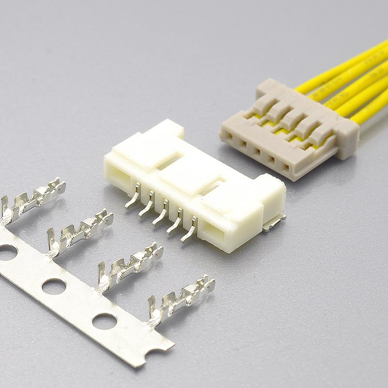
The DF14 is the rare 1.25mm connector that comes in two board-mounted heights: the standard on-board type (DF14 with a locating boss, DF14A without) at 2.5mm, and the offset type (DF14H) at 1.6mm. Same pitch, same contact system, same 1A/150V rating — and two different board-level decisions.
- If your design is the 2.5mm on-board type, the cross-reference case is strong, and unusually so: the second source's wafer dimensions reproduce the Hirose on-board header dimensions at every catalogued position count (more on that below).
- If your design depends on the 1.6mm offset height, no offset wafer is documented on the second-source side at all. That is not a sourcing detail — it is the difference between a drop-in part and a board respin.
So the honest first answer is: ask which architecture you have before you ask who can supply it.
I work on connector and harness programmes at KONNRA, which builds a documented cross-reference to this series (the KR1255). Here is what actually matters about the part.
First, the naming: the DF14 is a Hirose Electric series — part of Hirose's SignalBee™ signal-cable line — and there is no JST series designated DF14. The mix-up is common because both brands' small crimp connectors get called "JST connectors" in conversation (JST = Japan Solderless Terminal), and because Hirose's DF14 and JST's GH are both 1.25mm and look alike in a photograph. They do not mate.
And the DF14 is not the DF13, even though both are Hirose and both are 1.25mm. The DF13 is Hirose's miniature crimping line: 2 to 15, 20, 30 and 40 positions, one or two rows, 1.0A and 2.5A ratings, connector heights from 3.4mm to 5.4mm, in SMT and through-hole. The DF14 is single-row, low-profile, 1A, at 2.5mm or 1.6mm. Different footprints, different mating geometry. Writing "DF14/DF13" as if they were interchangeable is the second most common error on this series, right after "JST DF14".
The fastest way to tell them apart is one measurement: mated height above the board. 2.5mm or 1.6mm points at the DF14. 3.4mm or more points at the DF13.
What the Hirose DF14 is
- Pitch: 1.25mm, single row, wire-to-board — crimp socket to right-angle pin header
- Positions: thirteen catalogued counts — 2, 3, 4, 5, 6, 7, 8, 9, 10, 15, 20, 25, 30
- Board-mounted height: 2.5mm on-board · 1.6mm offset (
DF14H, 20 and 30 positions only) - Rated current: 1A per pin
- Rated voltage: 150V AC/DC
- Withstanding voltage: 500V AC per minute, no flashover or insulation breakdown
- Insulation resistance: 500MΩ min. at 100V DC
- Contact resistance: 30mΩ max., measured at 20mV or less with 1mA
- Operating temperature: −35°C to +85°C, and Hirose states explicitly that this includes the temperature rise caused by current flow
- Mating durability: 30 cycles with tin plating · 50 cycles with gold, contact resistance held to 30mΩ max afterwards
- Termination: crimping of discrete wire only — UL1571, AWG 26 to 32, jacket 0.54 to 1mm
- Header design: box-shaped four-wall header with retention tabs, to prevent prying and mis-insertion and to stop the socket rubbing the board
- Mounting: right-angle SMT, vacuum suction surface and embossed tape for pick-and-place (tube packaging also available on the on-board type)
- Insulator: beige polyamide, UL94V-0, RoHS2
- Crimp contacts:
DF14-2628SCF(26–28 AWG) andDF14-3032SCF(30–32 AWG), tin; the…Asuffix is the gold version - KONNRA equivalent: KR1255 (right-angle SMT wafer + housing + crimp terminal)
What the 1.6mm offset type actually costs
The offset header is not a lower version of the same footprint — it is a different board decision, in three ways:
- It is a different PCB pattern. Hirose publishes the offset mounting pattern separately from the on-board pattern, with its own dimensions. You cannot lay out an on-board footprint and expect a
DF14Hto land on it. - It is a 20- and 30-position part. Those are the only two counts catalogued. If your design needs 8 or 15 positions at 1.6mm, the answer is a packaging change, not a part-number change.
- It is supplied on tape only. The offset headers are catalogued in reels with a gold-plated embossed-tape specification, while the on-board header is available in both tape and tube. If your line hand-loads tube parts, the offset type removes that option.
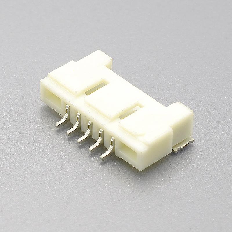
And on the cross-reference side, KONNRA documents a right-angle SMT wafer at a 2.5mm on-board height — the on-board architecture — and no offset (1.6mm) wafer at all. If your design is on the offset height, that is the first thing to raise, because no catalogue comparison will fix a board-level architecture gap.
One more thing about the offset type, stated carefully. Hirose's catalog shows the offset header sitting at the board edge rather than entirely on the board surface, with its own mounting pattern and the 1.6mm mated height. The catalog does not use the word "notch". Whether your particular board outline needs a cut-out for a DF14H is a mechanical question to settle against the DF14H drawing and the enclosure — not something to infer from the height figure. This is exactly the kind of assumption that turns into a respin.
Why the on-board case is unusually strong
When someone asks whether a second source is genuinely a drop-in, the useful evidence is dimensional, not electrical. On this series it is available:
- The crimp socket's contact field (
B) is 1.25mm × (positions − 1) — 1.25mm at 2 positions, 11.25mm at 10, 36.25mm at 30. Hirose's table reproduces that at every count. - The socket's overall length (
A) runs 3.20mm aboveB; the on-board header's overall length runs 6.20mm aboveB— 7.45mm at 2 positions, 42.45mm at 30. - The KR1255 wafer drawing lists header dimensions of 7.45, 8.70, 9.95, 11.20, 12.45, 13.70, 14.95, 16.20, 17.45, 23.70, 29.95, 36.20 and 42.45mm for 2 to 30 positions — the same numbers as Hirose's on-board header
Acolumn at every catalogued count, with matching contact-field dimensions from 1.25mm to 36.25mm.
That is the strongest single piece of evidence that the wafer is dimensioned to the DF14 on-board footprint, and it is also a cross-check you can run on any quotation: if a supplier quotes a different overall dimension for a given position count, one of the two numbers is wrong.
The part-number trap: one letter, two different jobs
DF14 A - 20 P - 1.25 H (##)
DF14— series- Configuration: blank = on-board with boss ·
A= on-board without boss ·H= offset - Number of contacts — 2 to 10, 15, 20, 25 or 30
- Connector type:
S= crimp socket (cable side) ·P= pin header (board side) 1.25— pitch- Contact type:
C= crimping socket ·H= right-angle SMT - Packaging — header:
(22)tin/tape ·(35)tin/tube ·(52)gold/tape ·(65)gold/tube. Socket:(10)bag of 100
The trap: the letter A does two different things depending on the part. On a header, a leading A means on-board without boss. On a contact, a trailing A means gold plated — DF14-2628SCFA versus DF14-2628SCF. Reading a trailing A as a configuration code, or a leading A as a plating code, is the most common part-number error on this series. It matters, because on this connector plating sets the durability rating: 30 cycles tin, 50 cycles gold.
Where the cross-reference stops being like-for-like
- Plating is the biggest gap. Hirose lists tin or gold for both the contact and the header, with plating thickness values of 0.1µm and 0.76µm. KONNRA documents tin over nickel, with no thickness figure in the product page, the specification PDF or the drawing. A gold-plated DF14 and a tin-plated equivalent are different parts for different mating-cycle budgets and contact-stability requirements. If your design assumed gold, say so in the enquiry.
- Durability agrees at 30 cycles — but the acceptance limit after cycling does not. Hirose holds contact resistance to 30mΩ max after the durability test. KONNRA permits 60mΩ max after 30 cycles, against a 30mΩ max initial value. If your assembly is re-mated in service, put the 60mΩ figure in your reliability budget, not the 30mΩ one.
- The humidity acceptance limit is twice as loose on the KONNRA side. Both run 96 hours at 40±2°C and 90–95% RH. Hirose requires contact resistance 30mΩ max and insulation resistance 500MΩ min afterwards — the same insulation resistance as the initial requirement. KONNRA permits 60mΩ max and 100MΩ min. For a humid-environment product this is the most consequential test-condition difference in the comparison.
- Temperature differs by design margin, and Hirose is the conservative one. Hirose: −35°C to +85°C, including current-flow temperature rise. KONNRA: −40°C to +105°C, backed by its own tests at −40±2°C and 105±2°C for 96 hours. Do not assume the wider range transfers to the Hirose part — and if you rely on the KONNRA figure, ask for the temperature-rise data behind it.
- The headline ratings agree; the measurement conditions behind them do not. Contact resistance is 30mΩ max on both sides — but Hirose measures at 20mV or less with 1mA, while KONNRA measures under a dry circuit at 20mV max and 100mA max (EIA-364-23C). The same number at a hundred times the current: neither is wrong, but they are not interchangeable evidence in a qualification report.
- Insertion and extraction force are published on different bases. Hirose gives a per-contact figure: 0.15N (15gf) min to 3N (300gf) max, measured with a 0.3mm square pin. KONNRA gives a per-connector figure that scales with position count — 2 positions: 1.60kgf max insertion / 0.10kgf min withdrawal; 10: 4.00 / 0.50; 20: 7.00 / 1.00; 30: 10.00 / 1.50 kgf. To compare, divide by the position count and convert units — and do that on your own assembly rather than trusting a side-by-side table that implies they are the same measurement.
- Position counts: thirteen catalogued versus a marketed 2–30 range. Hirose enumerates 2 to 10, 15, 20, 25 and 30. KONNRA markets 2–30 pin, and its drawing tabulates dimensions for 2 to 15, 20, 25 and 30 — including 11, 12, 13 and 14, four counts Hirose does not catalogue. Confirm which counts are actually tooled before a drawing depends on an intermediate count.
- One genuine agreement worth recording, because the opposite is common: the withstanding voltage matches exactly. Hirose: 500V AC per minute, no flashover or insulation breakdown. KONNRA's product page, specification PDF and drawing all say 500V AC per minute, applied for one minute between adjacent terminals or between terminal and ground, with no breakdown and no flashover (EIA-364-20A). 500V is a genuine dielectric-withstand figure here, not a rated voltage copied into the wrong field. The rated voltage, 150V AC/DC, agrees on both sides too.
- Hirose's own two documents disagree with each other on manual soldering. The DF14 catalog states 350°C for 3 seconds; the DF14 product guideline PDF states 290°C for 2 seconds, plus a reflow profile of 150°C pre-heating for 60–120 seconds and 250°C for 10 seconds maximum at the soldering area, up to 2 reflow cycles, with a recommended screen thickness of 0.15–0.2mm and a board warpage limit of 0.03mm. KONNRA documents one reflow profile — pre-heat 150–200°C for 90–120 seconds, 230°C minimum for 20–40 seconds, peak 255±5°C for 5–10 seconds — with no cycle count and no screen thickness stated. Run your own profile check; the two are not the same statement.
Design and handling notes that account for most field problems
- Insert and remove parallel to the board. Hirose states in both the catalog and the guideline that the connector must not be inserted or removed at 30° or greater, and that doing so causes contact deformation or case damage.
- The four-wall header is there to prevent prying. The walls exist so the socket cannot be worked in at an angle or rub the board. Treating them as cosmetic is how retention tabs get peeled.
- The retention tabs are a solder-peel defence, not a lock. If your assembly is handled or the cable is routed with strain, that is a locking requirement — and KONNRA documents a locking version of the same 1.25mm DF14 interface as the KR1258 series (2–30 positions, 1A, 150V, insulation O.D. 0.90mm max against the KR1255's 1.00mm, −40°C to +105°C). Hirose's DF14 catalog lists no locking variant, so this is a case where the second source covers a requirement the original does not.
- The boss hole is optional — order the version your pattern is laid out for. The with-boss header needs a φ1.1 +0.1mm hole; the without-boss version needs none.
- Board warpage matters at this pitch. Hirose's limit is 0.03mm at the connector. At 1.25mm pitch, a coplanarity problem invisible on a 2.54mm part becomes a missing solder joint.
- The crimp is the reliability. Hirose states that crimp height determines crimping quality, that the setting varies between tin and gold terminals on the same wire, and that it varies with strand construction at the same sectional area. KONNRA publishes the same conclusion as dimensions — separate crimp heights for 26, 28, 30 and 32 AWG and minimum crimp strengths from 2.27kgf down to 0.7kgf. Ask for the crimp condition table, whichever brand you buy.
- Tooling and warranty. Hirose specifies its own applicators (
AP105-DF14-2628S/AP105-DF14-3032S) and press (CM-105C) and states the warranty does not cover problems caused by tools other than those it specifies. KONNRA does not document crimp tooling for the KR1255 terminal. If you build harnesses in-house, ask before committing the line.
What to send for a cross-reference check
- The original Hirose part number, if you have it —
DF14-20S-1.25C(10),DF14-20P-1.25H(52),DF14A-30P-1.25H(65), or the contactDF14-2628SCFA - Position count — Hirose catalogues thirteen: 2 to 10, 15, 20, 25, 30
- Mounting style and board height — on-board 2.5mm, or offset 1.6mm. This is the question that decides whether a drop-in is possible
- Termination type — crimped discrete wire; confirm whether your harness is built in-house or bought finished
- Wire specification — gauge, strand construction and jacket diameter (UL1571, 0.54–1mm across 26–32 AWG)
- Plating — tin or gold. This is where the cross-reference most often stops being like-for-like
- Application, annual volume, and whether you buy connectors or finished harnesses
- A drawing or photo if the part number is unreadable
Three things get confirmed against Hirose's own documentation: the board height and mounting style your suffix corresponds to, the plating and durability budget your application needs, and whether the position count is available in tooling.
And one clarification that saves time: the DF14 does not connect to an FPC. Hirose lists its termination method as crimping, the recommended wire as discrete wire, and its product-number structure has one cable-side type — the crimping socket (C) — with no FPC plug. FPC and micro-coaxial termination belong to the DF19, which is a 1.0mm series and a different interface. "DF14 with FPC" is a recurring mistake, and it usually traces back to a requirement that was mis-transcribed early.
Full technical write-up: Hirose DF14 Connector Complete Guide
Disclosure: I work with KONNRA, which manufactures the KR1255 cross-reference. The Hirose figures above are taken from Hirose Electric's published DF14 series page, DF14 catalog and DF14 product guideline; the KONNRA figures are from our published KR1255 documentation and specification. Where the two disagree — or where one source contradicts itself — I have flagged the difference rather than averaged it, and I have marked a parameter as not documented rather than estimating it.
https://konnra.com/hirose-df14-connector-complete-guide/
Dongguan Konnra Electronics Co., Ltd